Folding tower
a technology of supporting structure and tower, applied in the direction of foundation engineering, mechanical equipment, machines/engines, etc., can solve the problems of complex structure, large crane, high cost, and difficulty in adjusting the height of the tower, etc., to achieve the effect of reducing the risk of falling, raising and lowering the tower in a harsh environment in typically remote areas
- Summary
- Abstract
- Description
- Claims
- Application Information
AI Technical Summary
Benefits of technology
Problems solved by technology
Method used
Image

Examples
Embodiment Construction
” one will understand how the features of the system and methods provide several advantages over traditional systems and methods.
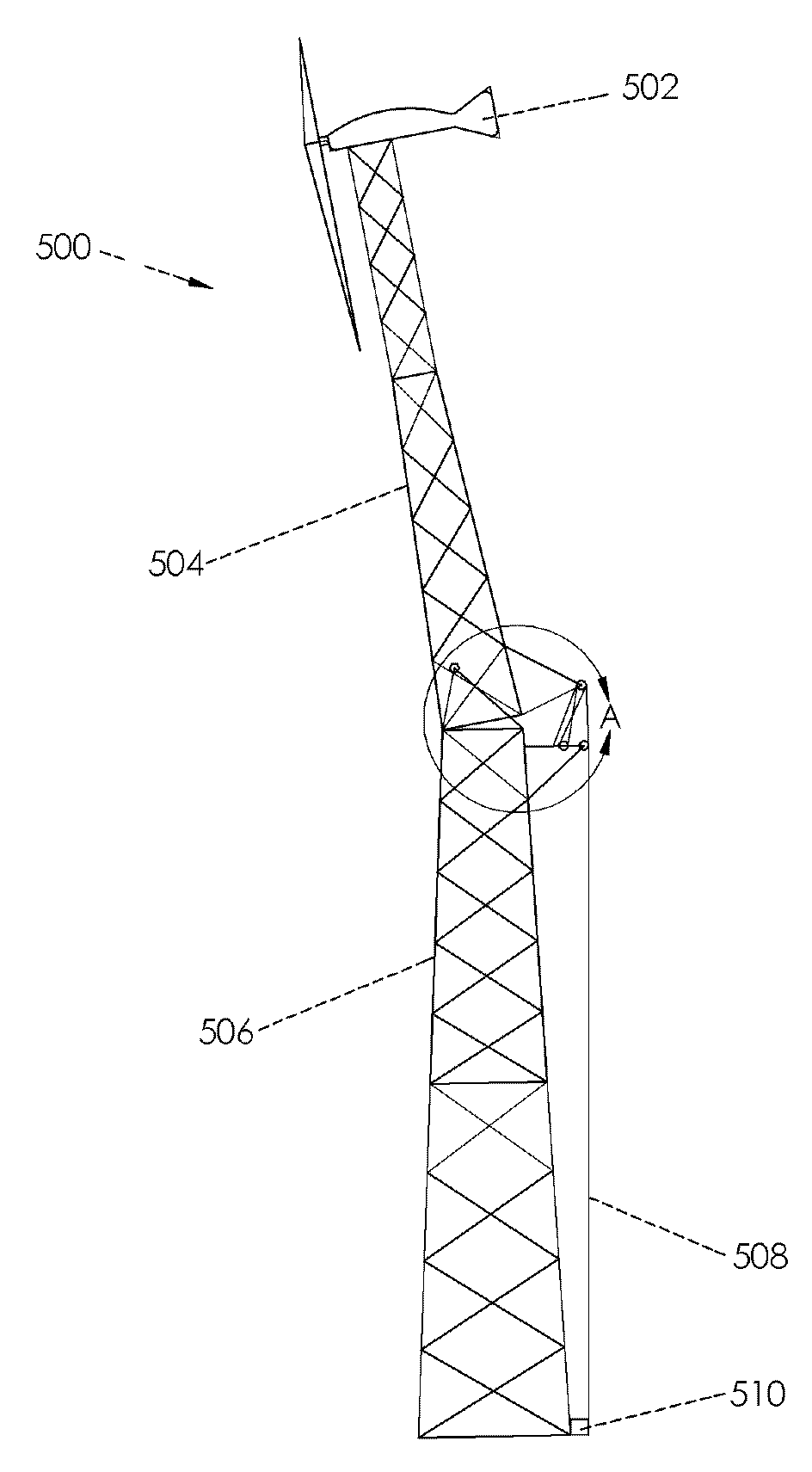
[0017]Embodiments disclosed herein incorporate a novel tower design, novel foundation, and installation method. An objective of the embodiments disclosed herein is to lower the installed cost of the tower as well as the cost to access equipment secured to the top of the tower to perform maintenance and repairs, and to be able to lower the equipment to the ground during extreme storms, such as hurricanes and tornados. These embodiments lower the cost of the tower at least three ways: 1. eliminating the need for a crane, 2. eliminating the need for concrete, and 3. reducing the time it takes to raise the tower. In one embodiment a tower is designed to be a tower for wind turbines, which benefit from high towers and require periodic access to the turbine for maintenance.
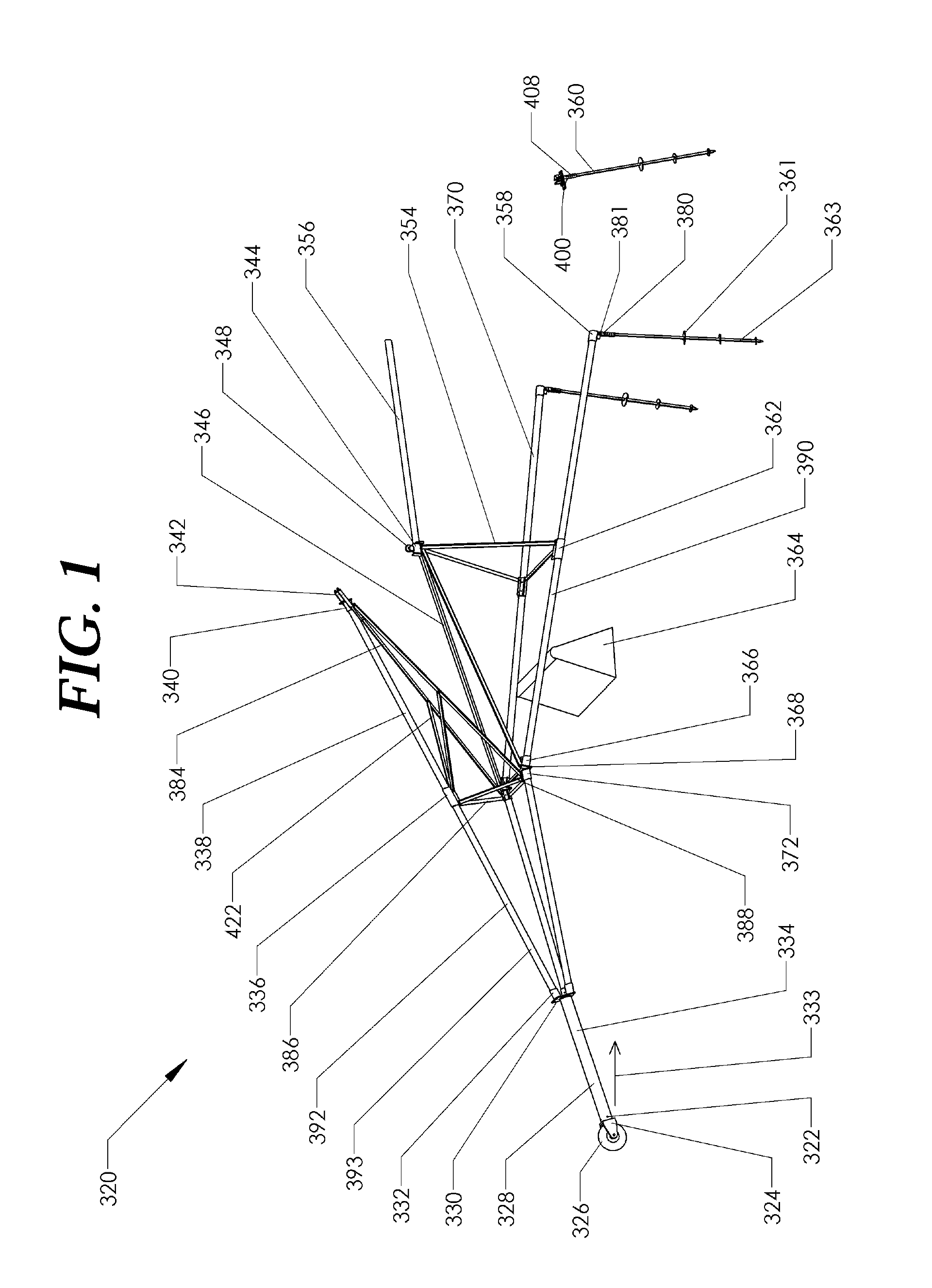
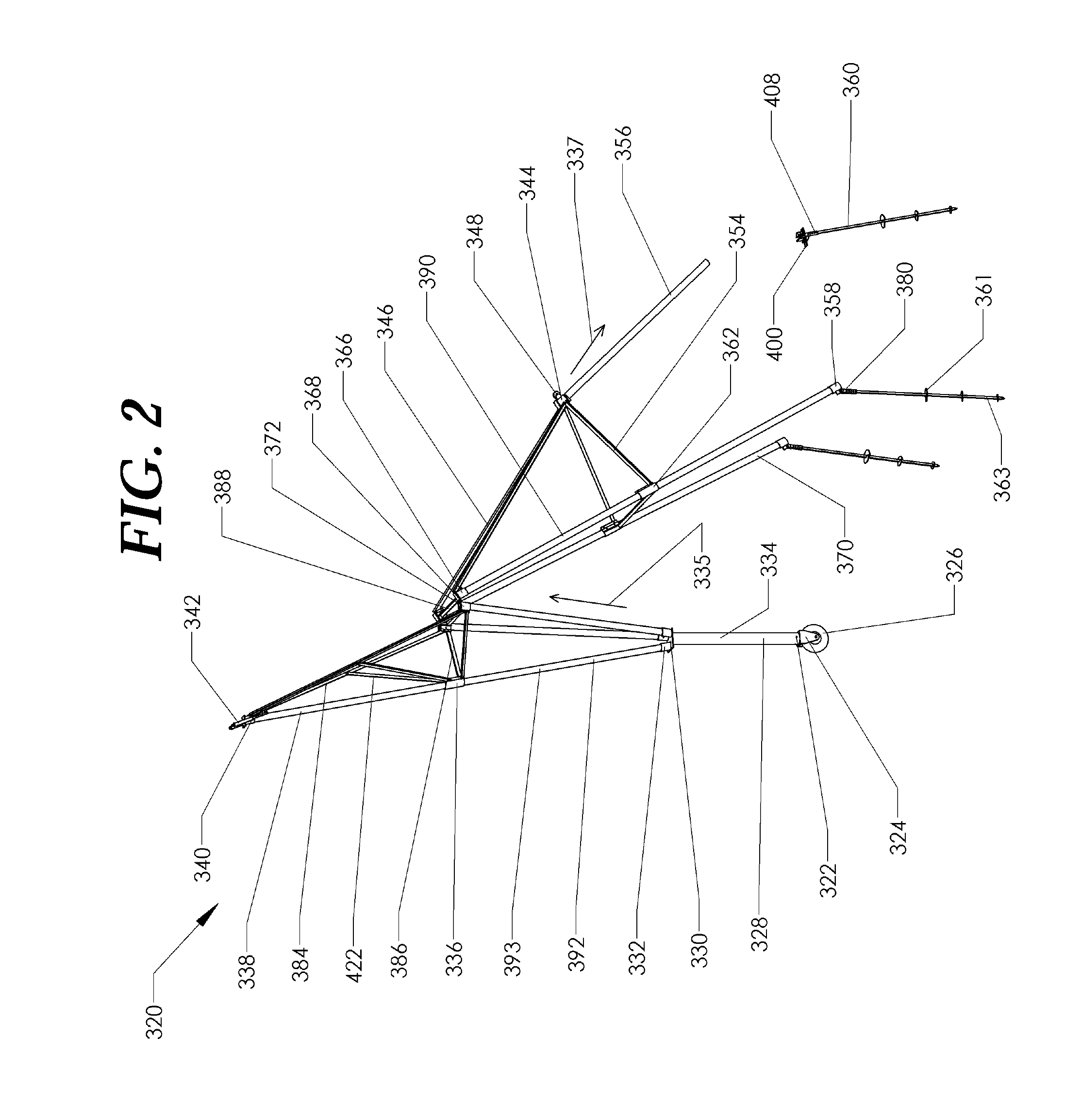
[0018]In one aspect, a folding tower, includes two tower sections, an upper section and a ...
PUM
 Abstract
Description
Claims
Application Information
 - R&D
- Intellectual Property
- Life Sciences
- Materials
- Tech Scout
- Unparalleled Data Quality
- Higher Quality Content
- 60% Fewer Hallucinations
Browse by: Latest US Patents, China's latest patents, Technical Efficacy Thesaurus, Application Domain, Technology Topic, Popular Technical Reports.
© 2025 PatSnap. All rights reserved.Legal|Privacy policy|Modern Slavery Act Transparency Statement|Sitemap|About US| Contact US: help@patsnap.com