Mixer and exhaust system

a technology of exhaust system and mixer, which is applied in the direction of mechanical equipment, machines/engines, transportation and packaging, etc., can solve the problems of considerable power drop of combustion engine, and the use of such mixers in the exhaust system is problematic, so as to reduce through-flow resistance and achieve adequate mixing effect

Active Publication Date: 2011-11-24
PUREM GMBH
View PDF4 Cites 18 Cited by
  • Summary
  • Abstract
  • Description
  • Claims
  • Application Information

AI Technical Summary

Benefits of technology

[0008]The present invention deals with the problem of providing an improved embodiment for a static mixer or for an exhaust system equipped with such, which is more preferably characterized in that the mixer on the one hand has an adequate mixing effect even at lower flow velocities while on the other hand it has a reduced through-flow resistance, particularly at higher flow velocities.

Problems solved by technology

The use of such mixers in the exhaust system however is problematic.
At higher flow velocities, this leads to a considerable drop in power of the combustion engine.

Method used


Image

  • Mixer and exhaust system
  • Mixer and exhaust system
  • Mixer and exhaust system

Examples


Embodiment Construction

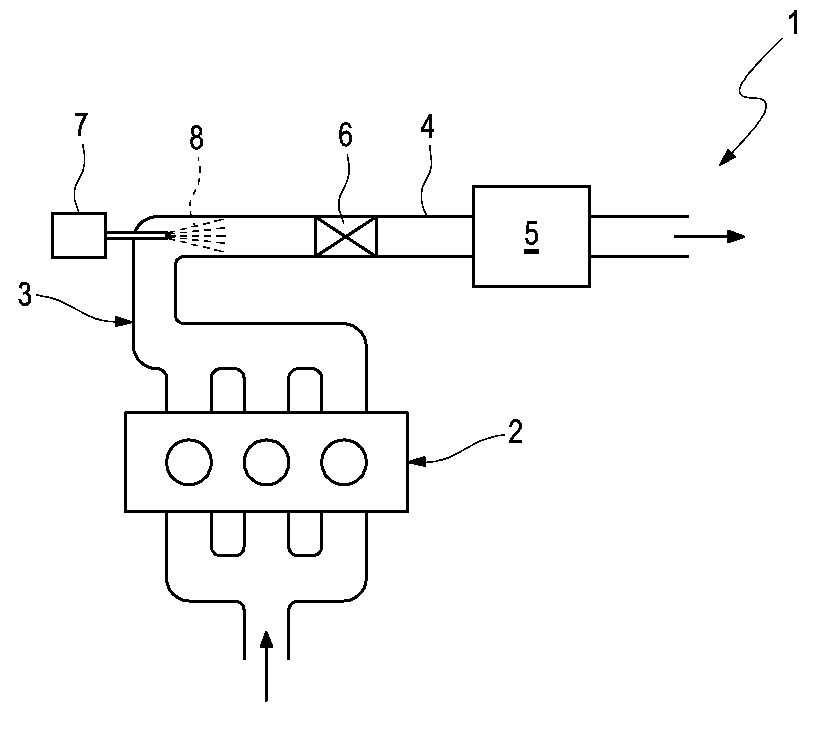
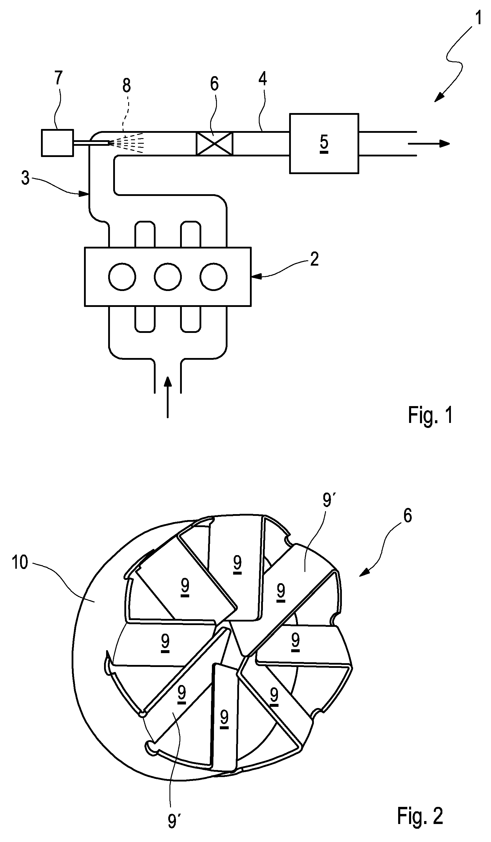
[0028]Referring to the drawings in particular, according to FIG. 1, an exhaust system 1 is provided for discharge of exhaust gases of a combustion engine 2. The exhaust system 1 can be arranged in a motor vehicle. The exhaust system 1 comprises an exhaust gas train 3, having an exhaust line 4 and at least one exhaust gas treatment device 5 which is incorporated in the exhaust line 4. In addition, the exhaust system 1 comprises a static mixer 6 which is likewise arranged in the exhaust line 4.

[0029]Preferentially, the exhaust gas treatment device 5 is designed as SCR-catalytic converter which in the following is likewise designated with 5. In this case, the mixer 6 is arranged in the exhaust line 4 upstream of the SCR-catalytic converter 5. In addition to this, the exhaust system 1 shown comprises an injection device 7, with the help of which a liquid reduction agent 8 can be injected into the exhaust gas train 3 or in the exhaust line 4. The mixer 6 in this case is positioned in the...


PUM

PropertyMeasurementUnit
temperatureaaaaaaaaaa
through-flow resistanceaaaaaaaaaa
resistanceaaaaaaaaaa

Abstract

A static mixer for the through-mixing of a flow in a line conducting the flow, more preferably of an exhaust system of a combustion engine with several guide vanes. To create adequate through-mixing at low flow velocity and a through-flow resistance that is not too high at high flow velocity, the guide vanes are produced of a shape memory alloy wherein below a predetermined limit temperature the guide vanes have at least one low-temperature shape and above the limit temperature the guide vanes have at least one high-temperature shape, which differs from the low-temperature shape through a reduced through-flow resistance of the mixer.

Description

CROSS REFERENCE TO RELATED APPLICATIONS[0001]This application claims the benefit of priority under 35 U.S.C. §119 of German Patent Application 10 2010 021 040.4 filed May 19, 2010, the entire contents of which are incorporated herein by reference.FIELD OF THE INVENTION[0002]The present invention relates to a static mixer for the through-mixing of a flow in a line conducting the flow, particularly of an exhaust system of a combustion engine, the static mixer including several guide vanes. The invention additionally relates to an exhaust system for a combustion engine equipped with such a mixer, more preferably of a motor vehicle.BACKGROUND OF THE INVENTION[0003]In many technical fields it is required to homogenize a multi-phase flow. To this end, a mixer can be arranged in a stationary manner in a line conducting the flow, through which mixer the flow flows and in the process mixes the individual phases of the flow, which leads to the desired homogenization. Such a mixer arranged in ...

Claims


Application Information

Patent Timeline
Patent Type & Authority Applications(United States)
IPC IPC(8): F01N3/035F01N3/18F01N3/10B01F5/06F01N13/00
CPCB01D2251/20B01D2251/208B01F3/04049B01F5/0451F01N2610/02B01F2005/0628B01F2005/0639F01N3/2892F01N2240/20B01F5/0617Y02A50/20B01F23/2132B01F25/3131B01F25/4311B01F25/4315B01F25/431974
Inventor JEBASINSKI, ROLF
Owner PUREM GMBH
Why Eureka
Try Eureka