
Mechanism for activating a plurality of downhole devices

a technology of downhole devices and actuators, which is applied in the field of hydrocarbon recovery, can solve the problems of finite number of restrictions/ball sizes that can be implemented, potentially costly intervention, and inability to reliably activate the mechanism, and achieve the effect of convenient and reliable deployment and removal

Active Publication Date: 2011-11-24
SCHLUMBERGER TECH CORP
View PDF4 Cites 147 Cited by
  • Summary
  • Abstract
  • Description
  • Claims
  • Application Information

AI Technical Summary

Benefits of technology

[0010]In view of the above, there is a need for an improved mechanism which permits selective activation of multiple downhole devices without comprimising fullbore diameter. It is also preferable that one can do so

Problems solved by technology

To isolate and treat each zone separately, the prior art mechanisms have been very time consuming and expensive among other drawbacks.
The drawbacks of the graduated ball activation system are that there are only a finite number of restrictions / ball sizes that can be implemented.
After activation, the balls have to be dissolved or milled to gain access to the sections therebelow, which can lead to a potentially costly intervention.
In these embodiments, common concerns are the possible damage of control lines during run-in-hole, especially in horizontal wells.
A damaged control line means that only those lines below the damaged zone can be produced, severely impacting the total potential production from the well, possibly rendering it uneconomical.
Another drawback of such designs is that as the thickness of the valve increases, the internal diameter of the valve decreases in order to accommodate the complex hydraulic mechanisms in the valve.

Method used


Image

  • Mechanism for activating a plurality of downhole devices
  • Mechanism for activating a plurality of downhole devices
  • Mechanism for activating a plurality of downhole devices

Examples


second embodiment

A Second Embodiment

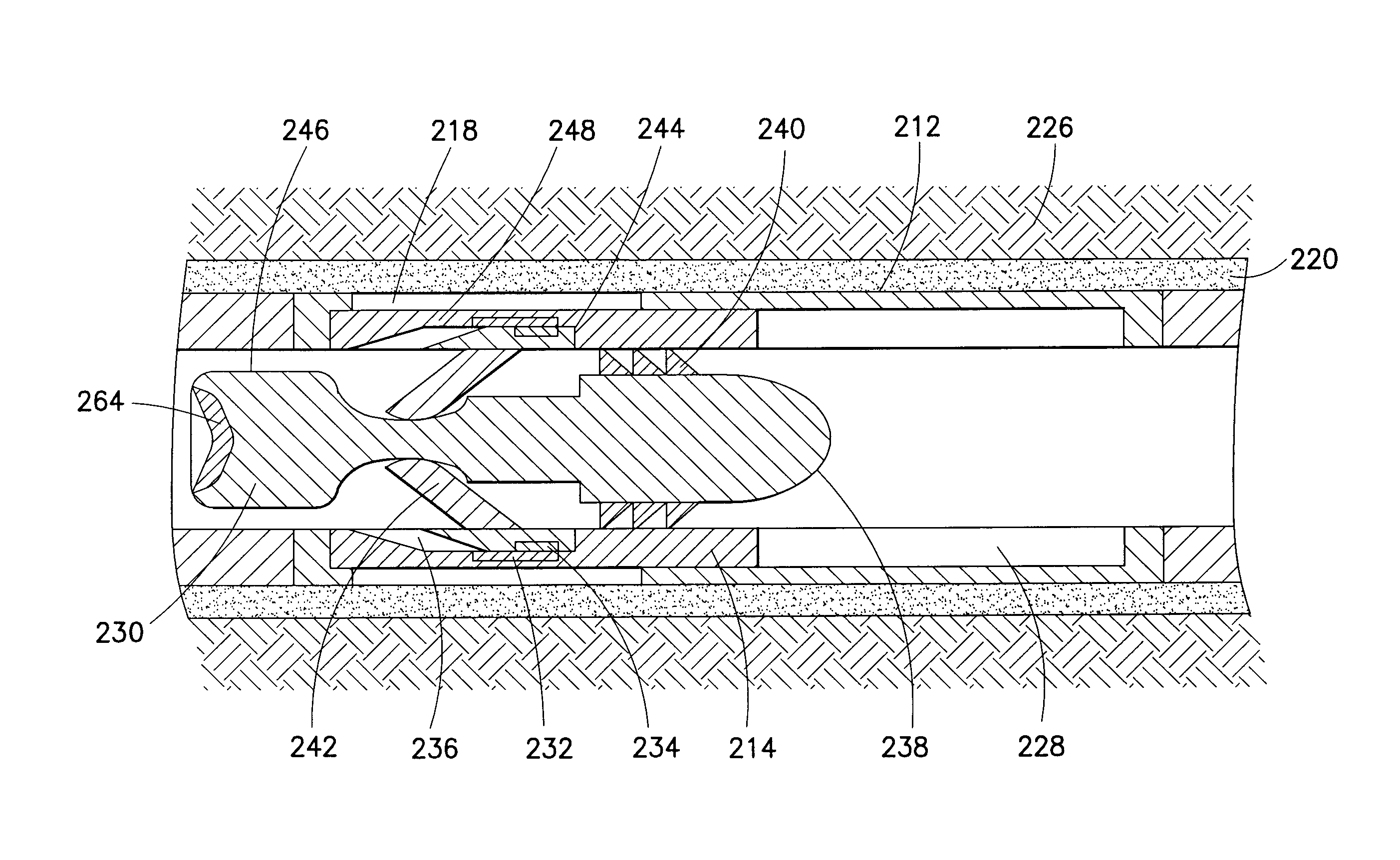
[0044]Turning to FIGS. 7 and 8, another embodiment of a valve 212 and dart 230 in accordance with the subject technology are shown. The valve 212 and dart 230 are similar to the valve 112 and dart 130 described above, and therefore like reference numerals preceded by the numeral “2” instead of the numeral “1” are used to indicate like elements. A primary difference of the dart 230 in comparison to the dart 130 is that the dart 230 includes a tail block 246 and modified mounting of the arms 242 to facilitate retrieval of the dart 230.

[0045]FIG. 7 shows the dart 230 engaged with the sliding sleeve 214 in the closed position. FIG. 8 shows the dart 230 still engaged with the sleeve 214 but with the sliding sleeve 214 in the open position after the dart 230 is pushed down by fluid pressure. The engagement by mutual attraction of matched magnets 232, 234 on the sleeve 214 and arm tips 244, respectively, is again utilized. However, the arms 242 are mounted to the body 23...

third embodiment

A Third Embodiment

[0050]Turning to FIGS. 10 and 11, another embodiment of a dart 330 in accordance with the subject technology is shown being deployed in a valve. The dart 330 is similar to the darts 130, 230 described above, and therefore like reference numerals preceded by the numeral “3” instead of the numerals “1” or “2” are used to indicate like elements. A primary difference of the dart 330 in comparison to the darts 130, 230 is that the dart 330 includes a secondary latching action to activate movement of components such as seals 370 that engage the valve 312.

[0051]Similar to above, correlated magnets 332, 334 on the sleeve 314 and arms 342, respectively, are used to initiate the secondary latching on the valve 312. The body 338 of the dart 330 forms a piloting mandrel or guide 372 to which the arms 342 pivotally mount. The arms 342 retain a plunger 374 when in the neutral position. The plunger 374 has a proximal head 376 with an opposing stem 378 extending therefrom such tha...


PUM


Abstract

A mechanism for selectively activating a plurality of downhole pathways including a) a valve having: i) a sleeve coupled for movement between an open and normally closed position; and ii) a valve magnet set mounted to the sleeve; and b) a dart for pumping in hole including a dart magnet set matched to the valve magnet set such that the dart couples to the valve when in close proximity and, in turn, the sleeve moves from the closed position to the open position.

Description

BACKGROUND OF THE DISCLOSURE[0001]1. Field of the Disclosure[0002]The subject disclosure relates generally to recovery of hydrocarbons in subterranean formations, and more particularly to a mechanism for activating a plurality of downhole devices such as when creation of multiple production zones is desired.[0003]2. Background of the Related Art[0004]There are many situations when one would like to selectively activate multiple downhole devices. For example, in typical wellbore operations, various treatment fluids may be pumped into the well and eventually into the formation to restore or enhance the productivity of the well. For example, a non-reactive fracturing fluid may be pumped into the wellbore to initiate and propagate fractures in the formation thus providing flow channels to facilitate movement of the hydrocarbons to the wellbore so that the hydrocarbons may be pumped from the well.[0005]In such fracturing operations, the fracturing fluid is hydraulically injected into a w...

Claims


Application Information

Patent Timeline
IPC IPC(8): E21B34/06E21B34/00E21B31/06
CPCE21B23/00E21B2034/007E21B43/14E21B34/14E21B2200/06E21B34/142E21B33/14
Inventor CHEN, KUO-CHIANGTASHIRO, HITOSHICOOPER, IAINPABON, JAHIROCALAN, MURAT
Owner SCHLUMBERGER TECH CORP
Features
  • Generate Ideas
  • Intellectual Property
  • Life Sciences
  • Materials
  • Tech Scout
  • Unparalleled Data Quality
  • Higher Quality Content
  • 60% Fewer Hallucinations
Learn More