
Deflection Mirror and Device for Laser Inscribing with the Deflection Mirror Unit

Inactive Publication Date: 2011-11-24
NANOSEC GES FUR NANOTECH & DER SICHERHEITSTECHN
View PDF10 Cites 8 Cited by
  • Summary
  • Abstract
  • Description
  • Claims
  • Application Information

AI Technical Summary

Benefits of technology

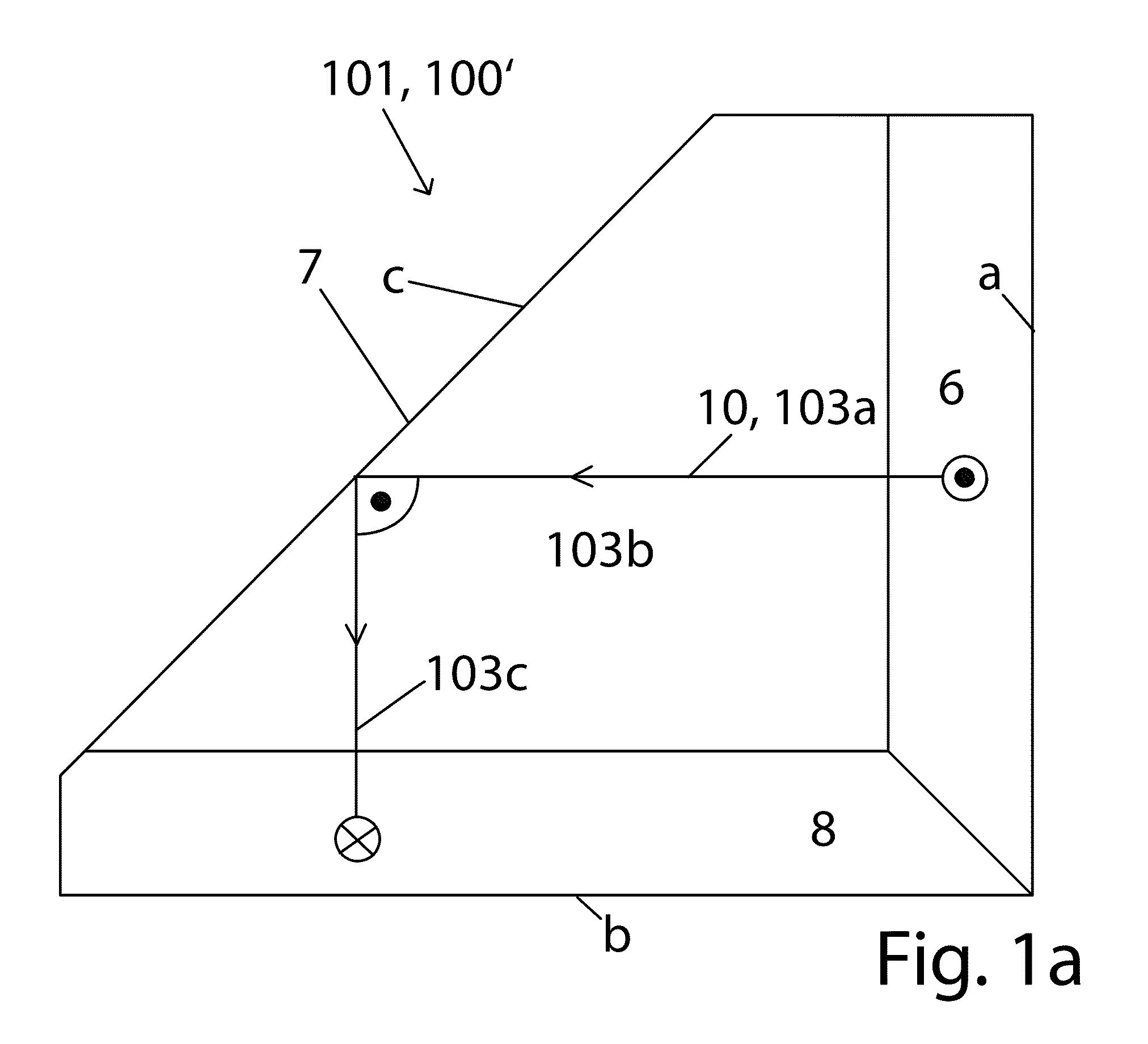
[0018]Thus it is the object of the invention to provide a deflection mirror unit and a laser inscribing device including the deflection mirror unit which are producible in a simple and cost effective manner and which simplify in particular the adjustment of the fixated deflection mirrors.
[0075]When the slanted prism depending on the direction of its affectivity causes a deflection in an X-direction this can be facilitated through respectively approaching another position through the card slide.

Problems solved by technology

This however causes relatively large overall dimensions of the laser inscribing device.
This adjustment complexity is very high when there are three non-moving deflection mirrors above the main plane and three non-moving deflection mirrors below the main plane and correct adjustment requires a substantial amount of time and skill.

Method used


Image

  • Deflection Mirror and Device for Laser Inscribing with the Deflection Mirror Unit
  • Deflection Mirror and Device for Laser Inscribing with the Deflection Mirror Unit
  • Deflection Mirror and Device for Laser Inscribing with the Deflection Mirror Unit

Examples


Embodiment Construction

[0085]The detailed description set forth below in connection with the appended drawings is intended as a description of presently preferred embodiments of the invention and does not represent the only forms in which the present invention may be constructed and / or utilized. The description sets forth the functions and the sequence of steps for constructing and operating the invention in connection with the illustrated embodiments.

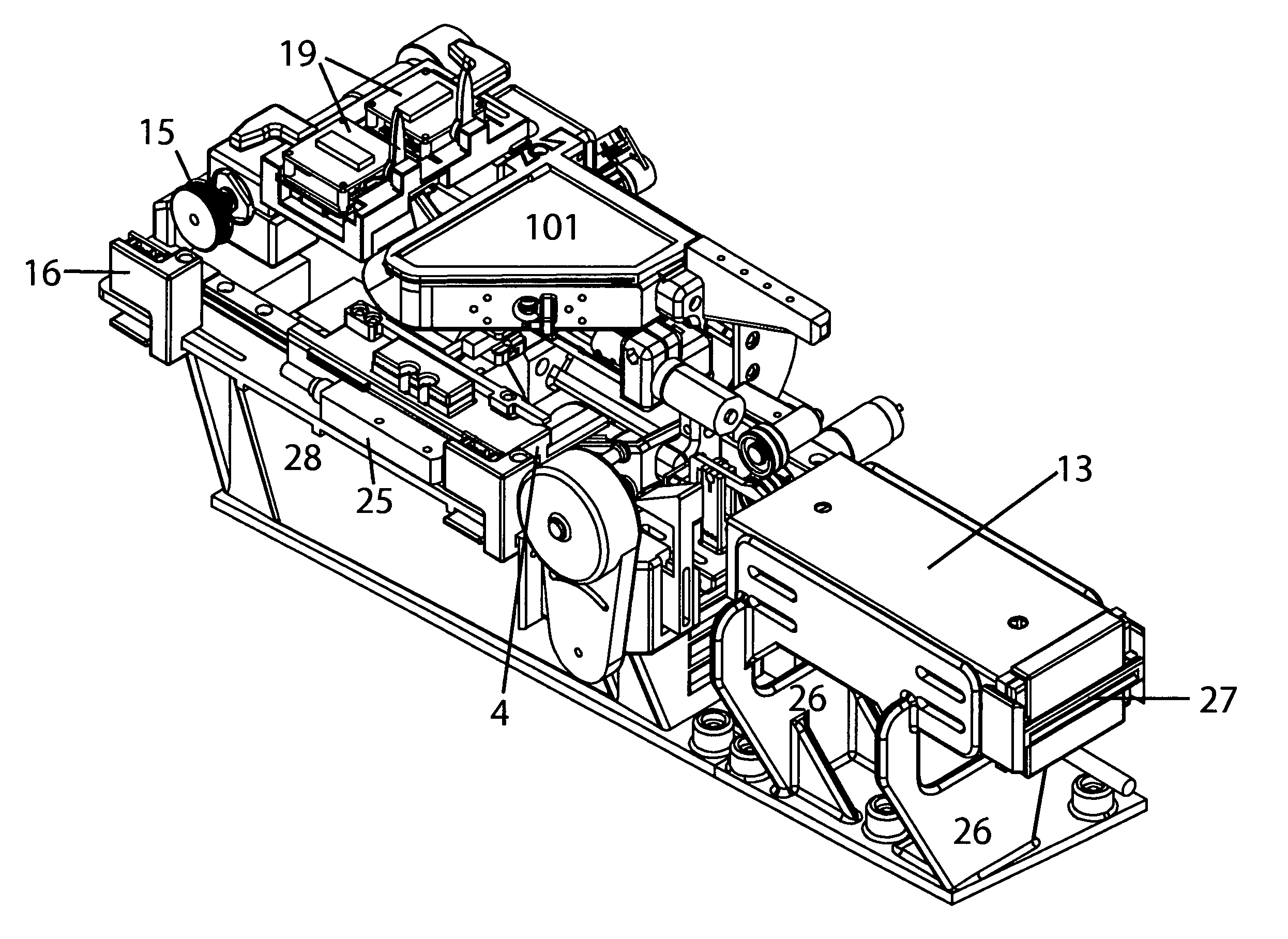
[0086]Initially the basic situation is illustrated in FIG. 3, wherein a card 200 is to be inscribed with the laser inscribing device according to FIG. 4, wherein the card lies flat in the laser inscribing device and is to be inscribed with the laser from a top and also from a bottom.

[0087]FIG. 3a illustrates the rectangular card 200 which is to be inscribed and which typically has circular corners and is received in a form locking manner in a card slide 4 which is movable in a controlled manner in X-direction, in this case the greater extension direction of ...


PUM

PropertyMeasurementUnit
Angleaaaaaaaaaa
Angleaaaaaaaaaa
Angleaaaaaaaaaa

Abstract

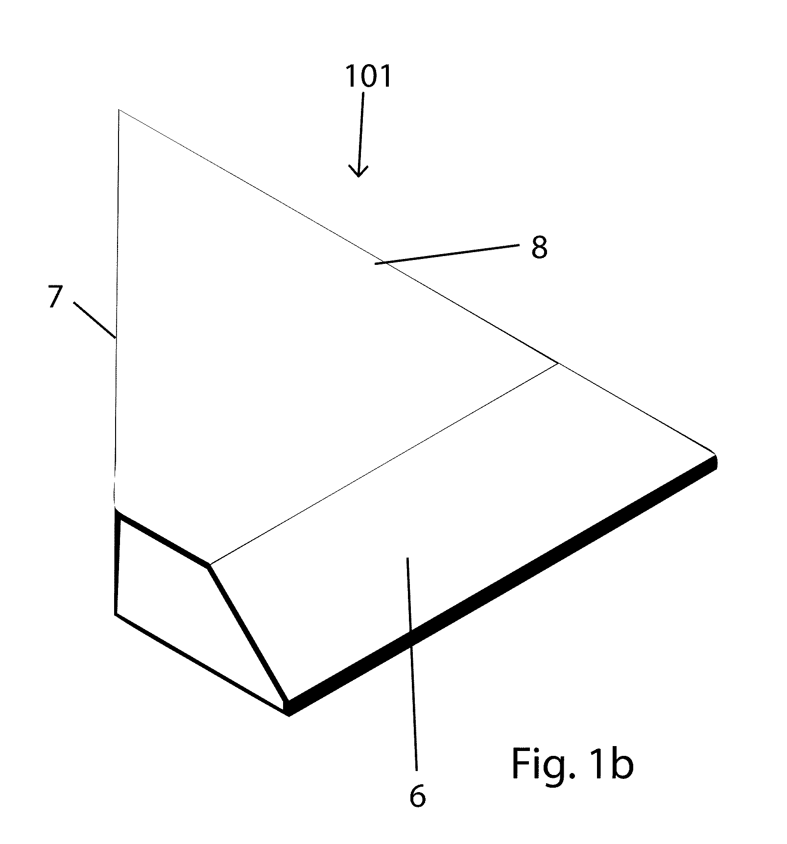
In order to keep the entire unit compact e.g. in a laser inscribing unit in spite of the laser beam impacting the card to be inscribed in an orthogonal manner a relatively large amount of beam deflections is necessary partially through mirrors that are fixated relative to one another. In order to minimize the assembly and adjustment complexity plural beam deflections are caused subsequent to one another through a prism element where the beam deflections are implemented through particular reflection surfaces. The prism element is received in a prism support which is configured to be pivoted and rotated in its entirety for assembly and adjustment purposes.

Description

CROSS REFERENCE TO RELATED APPLICATION[0001]This application takes priority from and claims the benefit under 35 U.S.C. §119 of European Patent Application Ser. No. 10163411.1 filed on May 20, 2010 the contents of which are hereby incorporated by reference.BACKGROUND OF THE INVENTION[0002]1. Field of the Invention[0003]The instant invention relates to a deflection mirror unit for three optical beam deflections of a laser beam and it relates to laser inscribing of card type substrates, e.g. ID cards, credit cards, check cards and similar flat planar objects with two main surfaces extending parallel to one another, wherein at least one of them shall be inscribed using the deflection mirror.[0004]2. Description of the Related Prior Art[0005]Inscribing in particular cards made from plastic material with a laser is well known in the art since the energy of the laser beam causes a carbonization and thus blackening of the carbon compounds of the substrate and thus a permanent coloration de...

Claims


Application Information

Patent Timeline
IPC IPC(8): B23K26/06G02B26/08
CPCB41M5/26G02B7/1822G02B7/1805
Inventor KREUTER, RUDIGER
Owner NANOSEC GES FUR NANOTECH & DER SICHERHEITSTECHN
Learn More