Chip-on-glass type liquid crystal display device

a liquid crystal display and chip-on-glass technology, applied in the direction of instruments, computing, electric digital data processing, etc., can solve the problems of deteriorating frequency characteristics, affecting the signal quality of the source driver, so as to achieve the effect of preventing signal distortion

Inactive Publication Date: 2011-11-24
SILICON WORKS CO LTD
View PDF5 Cites 15 Cited by
  • Summary
  • Abstract
  • Description
  • Claims
  • Application Information

AI Technical Summary

Benefits of technology

[0031]Accordingly, the present invention has been made in an effort to solve the problems occurring in the related art, and an object of the present invention is to provide a COG type liquid crystal display device using COG and point-to-point manners, which minimizes an reflected wave from an input terminal of a source driver IC by providing an impedance matching resistor on a front terminal of LOG or on an output terminal of a timing controller, thereby preventing signal distortion, and thus making it possible to express a high-resolution image.

Problems solved by technology

However, the liquid crystal display device using the COG manner additionally includes transmission lines called “LOG,” and impedance mismatching thereof becomes has been raised as a serious problem.
Especially, when the COG manner is employed in the liquid crystal display device as shown in FIG. 1, without any changes, data transmitted to the source driver ICs is distorted by the aforementioned mismatching, so that the frequency characteristic is deteriorated.
Especially, in a COG type liquid crystal display device, LOG has a very high impedance value of several tens to several hundreds of ohms, so that, when a termination resistor is included only in the source driver ICs, like in the conventional transmission scheme, it is difficult to achieve impedance matching of the input terminals of the source driver ICs, thereby deteriorating the frequency characteristic.
However, when the COG manner is used in a large-sized liquid crystal display device having high resolution and high quality, a very high operating frequency is required, and thus impedance matching at transmission lines is required, so that the conventional configuration including termination resistors at the reception terminals in source driver ICs is not suitable to implement a high-resolution high-quality image in a COG type liquid crystal display device.

Method used


Image

  • Chip-on-glass type liquid crystal display device
  • Chip-on-glass type liquid crystal display device
  • Chip-on-glass type liquid crystal display device

Examples


first embodiment

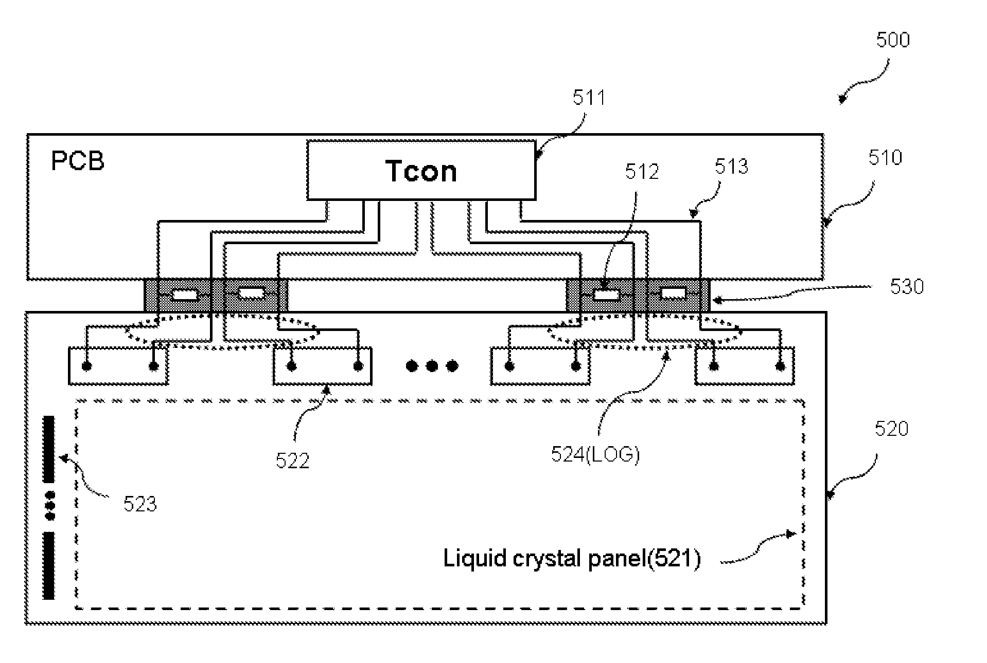
[0048]FIG. 5 is a view illustrating a chip-on-glass (COG) type liquid crystal display device according to the present invention.

[0049]As shown in FIG. 5, the COG type liquid crystal display device 500 according to the first embodiment of the present invention includes a printed circuit board (PCB) 510, a glass substrate 520, and a flexible printed circuit (FPC) 530.

[0050]The PCB 510 includes a timing controller 511. Also, on the PCB 510, transmission lines 513 are provided to transmit a pair of differential signals output from the timing controller 511 to the glass substrate. The timing controller 511 includes an impedance matching resistor 512 for impedance matching.

[0051]In addition, a liquid crystal panel 521, a plurality of source driver ICs 522, and a plurality of gate driver ICs 523 are mounted on the glass substrate 520 in a chip-one-glass manner.

[0052]The FPC 530 is a medium for electrical connection between the PCB 510 and the glass substrate 520. The characteristics and fu...

second embodiment

[0070]FIG. 8 is a view illustrating a COG type liquid crystal display device according to the present invention.

[0071]The COG type liquid crystal display device 500 shown in FIG. 8 according to the second embodiment of the present invention is the same as the COG type liquid crystal display device 500 shown in FIG. 5 according to the first embodiment of the present invention, except that the impedance matching resistor 512 is not provided on the output terminal of the timing controller 511, but is provided at the terminals of the transmission lines 513 on the PCB 510.

[0072]In order to transmit high-speed data, it is necessary to achieve impedance matching between PCB transmission lines and transmission lines on a glass substrate and an FPC, similarly between the timing controller and the PCB transmission lines.

[0073]Equation 3 expresses a reflection coefficient between the PCB transmission lines and the transmission lines on the glass substrate and FPC.

Γ=ZPCB-(ZFPC+RLOG)ZPCB+(ZFPC+R...

third embodiment

[0081]FIG. 11 is a view illustrating a COG type liquid crystal display device according to the present invention.

[0082]The COG type liquid crystal display device 500 shown in FIG. 11 according to the third embodiment of the present invention is the same as the COG type liquid crystal display device 500 shown in FIG. 8 according to the first embodiment of the present invention, except that the impedance matching resistor 512 is not provided at the terminals of the transmission lines 513 on the PCB 510, but is provided on the FPC 530.

[0083]Equation 4 expresses a reflection coefficient between the PCB transmission lines and the transmission lines on the glass substrate.

Γ=ZPCB-RLOGZPCB+RLOG(4)

[0084]Here, it is assumed that the impedance ZPCB of the PCB and the impedance ZFPC of the FPC have the same value to be matched with each other. In this case, in order for the reflection coefficient between the PCB transmission lines and the transmission lines on the glass substrate to be zero, th...


PUM


Abstract

A chip-on-glass (COG) type liquid crystal display device minimizes a reflected wave from an input terminal of a source driver IC, regardless of the resistance value of a transmission line on a glass substrate, through the use of impedance matching at a front terminal of an LOG and impedance matching at an output terminal of a timing controller, thereby enhancing the frequency characteristic while maintaining a slim and lightweight design, so that it is possible to express a high-resolution high-quality image.

Description

BACKGROUND OF THE INVENTION[0001]1. Field of the Invention[0002]The present invention relates to a liquid crystal display device, and more particularly, to a chip-on-glass (COG) type liquid crystal display device which minimizes a reflected wave from an input terminal of a source driver IC, regardless of the resistance value of a transmission line on a glass substrate, through the use of timing controller impedance matching and impedance matching at a front terminal of an LOG, thereby enhancing the frequency characteristic while maintaining a slim and lightweight design, so that it is possible to express a high-resolution high-quality image.[0003]2. Description of the Related Art[0004]In order to drive the row lines and column lines of a liquid crystal display (LCD) panel, source driver ICs and gate driver ICs are provided on the periphery of the panel. The gate driver ICs function to select picture elements to transmit image data, and actual image data and clock signals for picture...

Claims


Application Information

Patent Timeline
Patent Type & Authority Applications(United States)
IPC IPC(8): G06F3/038
CPCG09G2300/0408G02F1/136277G09G2370/08
Inventor OH, KWANG-ILKIM, JUN-HOCHOI, JUNG-HWAN
Owner SILICON WORKS CO LTD
Why Eureka
Try Eureka