Eureka AIR delivers breakthrough ideas for toughest innovation challenges, trusted by R&D personnel around the world.

Path rendering with path clipping

a path and path technology, applied in the field ofgraphics processing, can solve the problems of cpus relying on point, unacceptably poor antialiasing quality, and a substantial cpu burden, and achieve the effect of facilitating this usag

Active Publication Date: 2011-11-24
NVIDIA CORP
View PDF7 Cites 8 Cited by
  • Summary
  • Abstract
  • Description
  • Claims
  • Application Information

AI Technical Summary

Benefits of technology

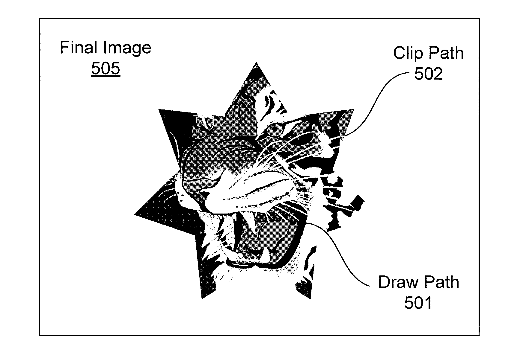
[0032]The stencil buffer includes clipped draw stencil buffer state indicating coverage for each individual draw path sample position that is clipped by a clip path and clip stencil buffer state indicating sample positions inside of the clip path. The clip stencil buffer state may be separately applied to different draw paths to generate respective clipped draw stencil buffer state. Regions of filled or stroked draw paths can be clipped by using the clip stencil buffer state. The clip stencil buffer state (for the clip path) and the clipped draw stencil buffer state can be stored in a single stencil buffer by segregating the clip ste

Problems solved by technology

Constructing the required tessellations of a path that is approximated by many short connected line segments can create a substantial CPU burden.
Tessellation is a fragile, often quite sequential, process that requires global inspection of the entire path.
A general problem with using a GPU to render paths is unacceptably poor antialiasing quality when compared to standard CPU-based methods.
The problem is that CPUs rely on point sampling for rasterization of triangular primitives with only 1 to 8 samples (often 4) per pixel.
Animating or editing paths is costly because it requires re-tessellating the entire path since the tessellation is resolution dependent, and in general it is very difficult to prove a local edit to a path will not cause a global change in the tessellation of the path.
In particular, this means the sub-paths of a path cannot be processed separately without first determining that no two sub-paths overlap.
These requirements, combined with the generally fragile and sequential nature of tessellation algorithms make path tessellation particularly expensive.
Unfortunately such tessellations are much less compact than the original path representations, particularly when curved path segments are involved.
Cached tessellations are also ineffective when paths are animated or rendered just once.
These offset curves are typically of much higher degree of complexity compared with the linear segments that are traced to generate the stroked path.
Determining whether or not each pixel is inside or outside of a stroked path to generate the stroking is mathematically complex.
While more mathematically complex path segments representations could be used to specify paths, in practice, existing standards limit themselves to the aforementioned path segment types.
In other words, it is quite unreasonable to try to determine exactly the boundary representation of such offset curves and then simply fill them.
Proper stroking is hard because of the mathematical complexity of the boundary of a path's stroke compared to a path's fill.
While approximations to the actual stroke boundary can reduce this complexity, such approximations have associated costs due to inaccuracy and the resulting expansion in the number of primitives that must be both stored and processed to render such approximated strokes.
In conventional path rendering, clipping and masking are relatively expensive operations.
In a path renderer based on tessellation, this can be quite expensive.

Method used


Image

  • Path rendering with path clipping
  • Path rendering with path clipping
  • Path rendering with path clipping

Examples


Embodiment Construction

[0049]In the following description, numerous specific details are set forth to provide a more thorough understanding of the present invention. However, it will be apparent to one of skill in the art that the present invention may be practiced without one or more of these specific details. In other instances, well-known features have not been described in order to avoid obscuring the present invention.

System Overview

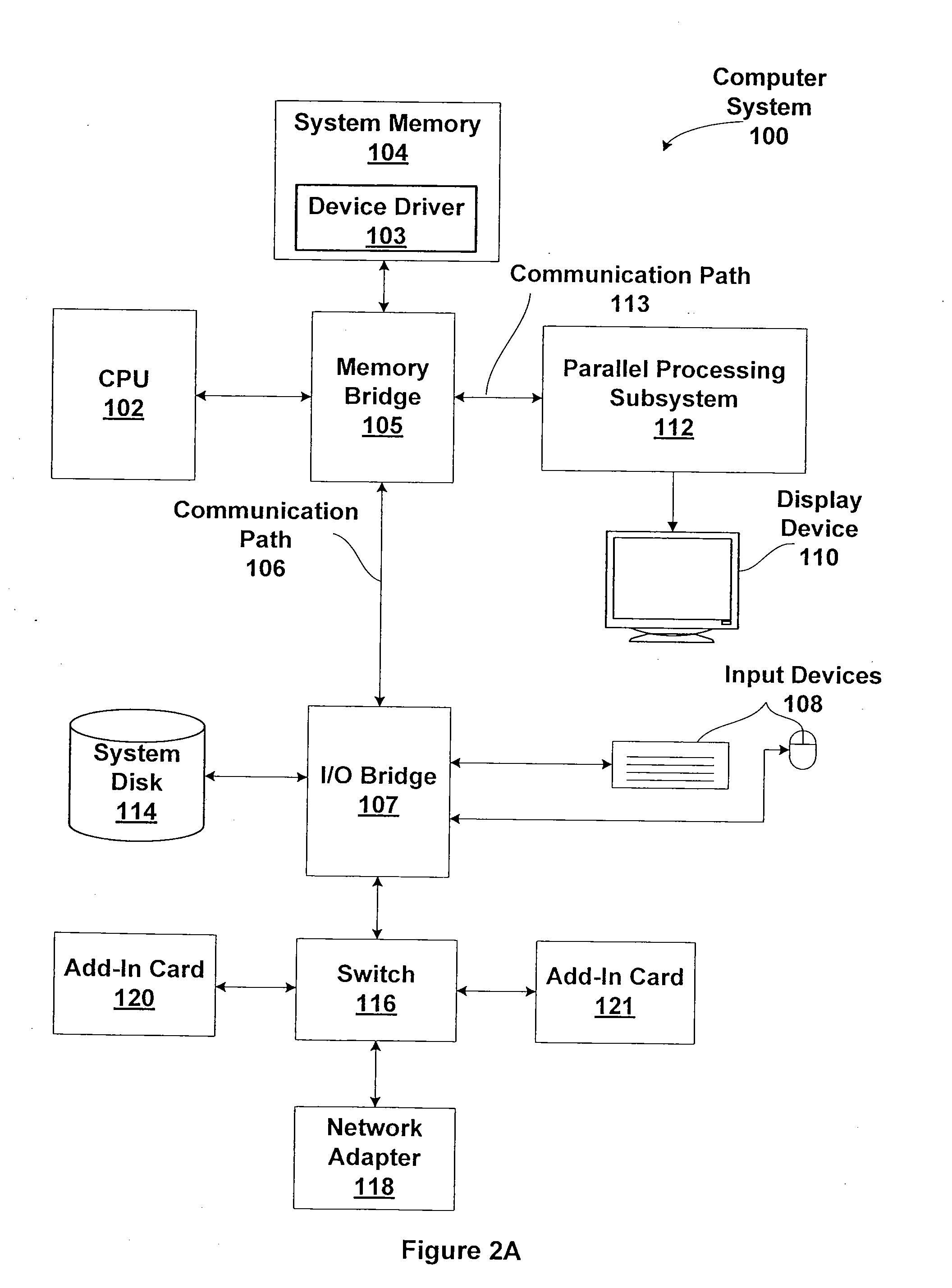
[0050]FIG. 2A is a block diagram illustrating a computer system 100 configured to implement one or more aspects of the present invention. Computer system 100 includes a central processing unit (CPU) 102 and a system memory 104 communicating via an interconnection path that may include a memory bridge 105. Memory bridge 105, which may be, e.g., a Northbridge chip, is connected via a bus or other communication path 106 (e.g., a HyperTransport link) to an I / O (input / output) bridge 107. I / O bridge 107, which may be, e.g., a Southbridge chip, receives user input from one or mo...


PUM


Abstract

One embodiment of the present invention sets forth a technique for rendering clipped paths by first generating clip stencil buffer state indicating pixels that are inside of the clip path. The clip stencil buffer state may also store an opacity value for each covered pixel to generate a mask that modulates the opacity of a draw path that is clipped. Clipped draw stencil buffer state is then generated indicating pixels of the draw path that should be covered based on the clip stencil buffer state and coverage of the draw path. The clipped draw path is then filled or stroked to produce the clipped draw path. The clip and draw paths may be filled or stroked without tessellating the paths. Path rendering may be accelerated when a GPU or other processor that is configured to perform operations to generate the clip stencil buffer state and the clipped draw stencil buffer state, and to fill or stroke the clipped draw path.

Description

CROSS-REFERENCE TO RELATED APPLICATIONS[0001]This application claims priority benefit to United States provisional patent application titled, “Path Rendering,” filed on May 21, 2010 and having Ser. No. 61 / 347,359 (Attorney Docket Number NVDA / SC-10-0110-US0). This related application is also hereby incorporated by reference in its entirety.BACKGROUND OF THE INVENTION[0002]1. Field of the Invention[0003]The present invention generally relates to graphics processing and more specifically to path rendering with path clipping.[0004]2. Description of the Related Art[0005]Path rendering is a style of resolution-independent two-dimensional (2D) rendering, often called “vector graphics,” that is the basis for a number of important rendering standards such as PostScript, Java 2D, Apple's Quartz 2D, OpenVG, PDF, TrueType fonts, OpenType fonts, PostScript fonts, Scalable Vector Graphics (SVG) web format, Microsoft's Silverlight and Adobe Flash for interactive web experiences, Open XML Paper Spe...

Claims


Application Information

Patent Timeline
IPC IPC(8): G09G5/02
CPCG06T11/203G06T15/005
Inventor KILGARD, MARK J.
Owner NVIDIA CORP
Why Eureka
Eureka Blog
Learn More