

Optical position measuring instrument
a technology of optical position measurement and measuring instrument, which is applied in the direction of instruments, measurement devices, sensor output conversion, etc., can solve the problems of poor signal quality of optical position measuring instruments, wave front deformation, and certain problems, and achieve the effect of ensuring the maximum interference contrast in the generation of interferential signals, high mounting tolerance, and reducing the number of optical components
- Summary
- Abstract
- Description
- Claims
- Application Information
AI Technical Summary
Benefits of technology
Problems solved by technology
Method used
Image

Examples
first exemplary embodiment
[0064]A first exemplary embodiment of the optical position measuring instrument of the present invention will now be explained in conjunction with FIGS. 2 through 5.
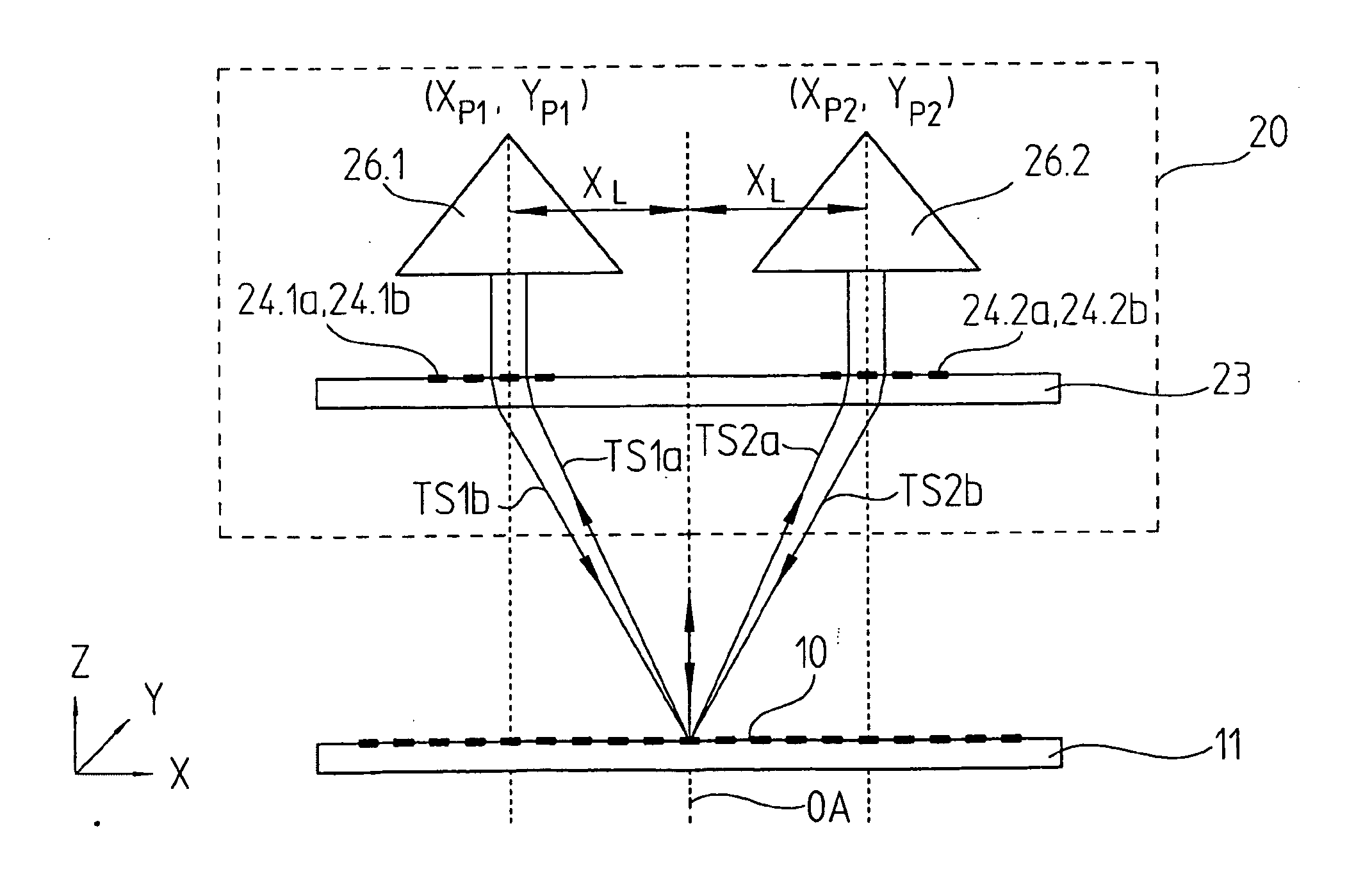
[0065]The fundamental scanning beam path of this exemplary embodiment will first be described with the aid of FIGS. 2, 3a and 3b. FIG. 2 shows a radial view of the corresponding optical position measuring instrument in the Y-Z plane; the (curved) measurement direction X is oriented perpendicular to that plane. FIGS. 3a and 3b show tangential sectional views of the optical position measuring instrument along the section lines AA′ and BB′ indicated in FIG. 2.
[0066]The optical position measuring instrument shown includes a scanning unit 20 and a scale 10 movable relative to it along the curved measurement direction X. The scale 10 in this case is embodied as a radial graduation, which is disposed on a graduated disk 11. The graduated disk rotates about the axis of rotation RA, about which the scale 10 or in other words the ...
second exemplary embodiment
[0096]The scanning beam path of a second exemplary embodiment of the optical position measuring instrument of the invention is schematically shown in FIGS. 6, 7a and 7b; these drawings correspond to the illustrations of the scanning beam path in the first exemplary embodiment. In FIG. 8, a wave front corrector is shown for the second embodiment of the optical position measuring instrument of the present invention. Below, only the definitive differences from the first example that has already been explained in detail will be discussed.
[0097]Thus it is provided on the one hand that the beam direction inverters, embodied as triple prisms in the first exemplary embodiment, are designed in an alternative way. Accordingly, in the second exemplary embodiment, the beam direction inverters are each embodied as a combination of a spherical lens 226.1a, 226.2a and a reflector mirror 226.1, 226.2 at the focal point of the lens. In the beam path, in the beam propagation direction, the beam first...
third exemplary embodiment
[0102]The fundamental construction of a third exemplary embodiment of the optical position measuring instrument of the invention is shown in FIGS. 9, 10a and 10b. These illustrations in turn correspond to the scanning beam path illustrations of the first and second exemplary embodiments of FIGS. 2-8. Below, only the definitive differences from the previous exemplary embodiments will be explained.
[0103]The beam emitted by a light source 321 embodied as a laser diode is collimated by a collimating optical system 322 and reaches the graduated disk 311. The scale 310 embodied as a radial graduation is in turn disposed on the graduated disk 311. The partial beams, deflected with the +1st and −1st orders of diffraction then strike respective first scanning gratings 324.1a and 324.2a, or in other words strike diffractive optical elements.
[0104]The scanning gratings 324.1a, 324.2a combine different optical functions in this exemplary embodiment; that is, once again they are embodied as diff...
PUM
 Abstract
Description
Claims
Application Information