
Photoreceptor diagnostic method based on detection of charge deficient spots

Active Publication Date: 2011-11-24
XEROX CORP
View PDF10 Cites 3 Cited by
  • Summary
  • Abstract
  • Description
  • Claims
  • Application Information

AI Technical Summary

Benefits of technology

[0006]The following presents a simplified summary in order to provide a basic understanding of some aspects of one or more embodiments of the invention. This summary is not an extensive overview, nor is it intended to identify key or critical elements of the invention nor to delineate the scope of the invention. Rather, its primary purpose is merely to present one or more concepts in simplified form as a prelude to the detailed description presented later.
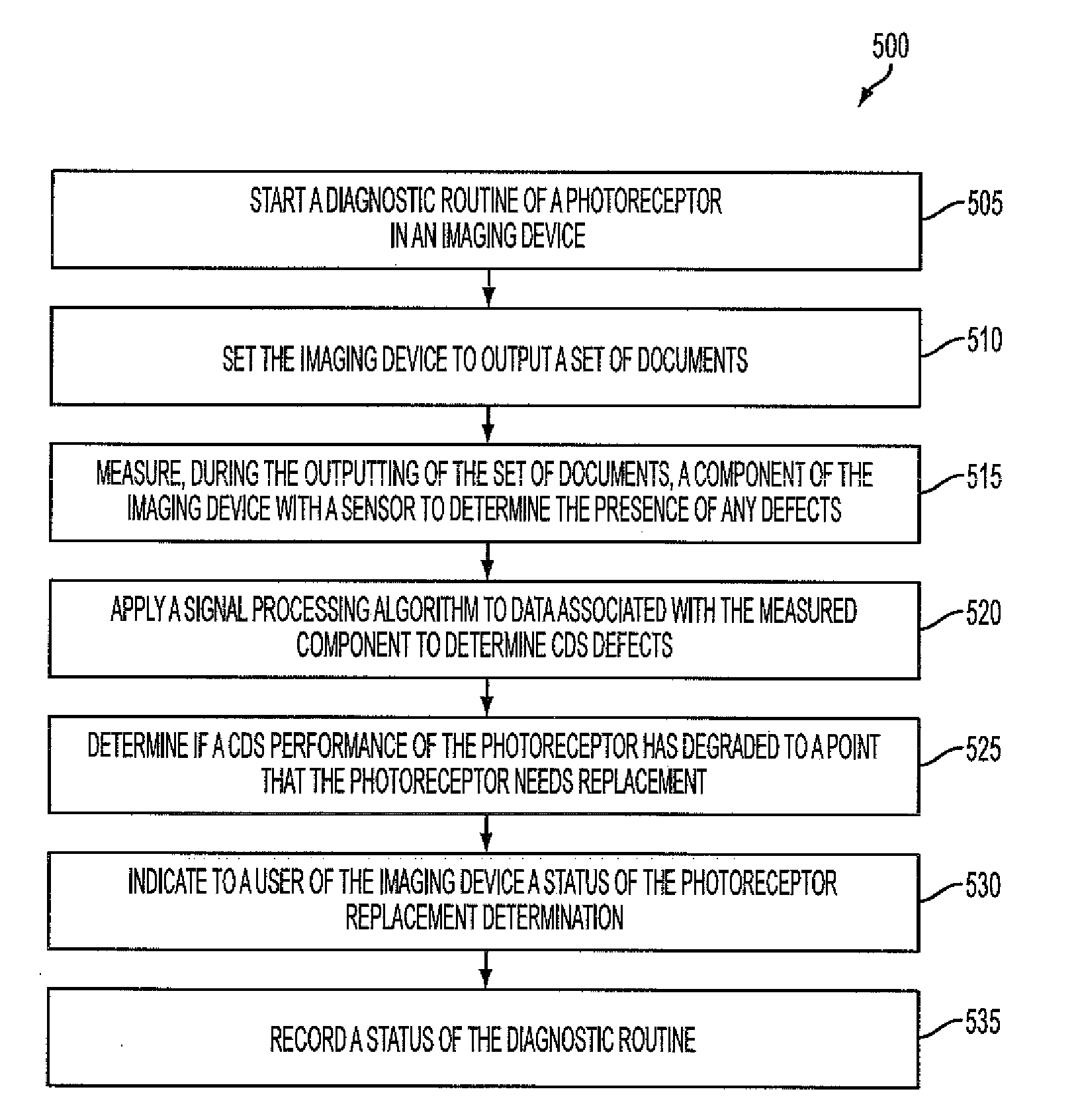
[0007]In accordance with the present teachings, a method of diagnosing a photoreceptor of a device is provided. The method comprises executing a set of cycles of the device, sensing a component associated with the device during each of the set of cycles to establish defect data, and processing the defect data

Problems solved by technology

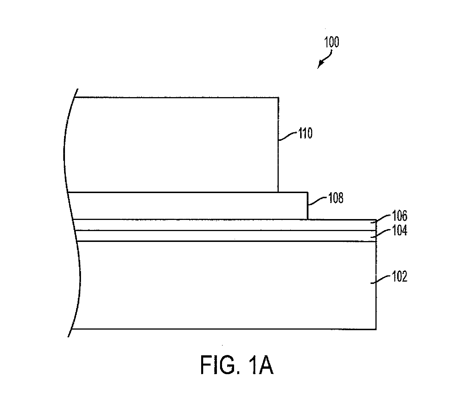
Over the lifecycle of the imaging device and corresponding photoreceptor, the CTL can deplete and reduce in thickness, which can cause the photoreceptor to be more susceptible to field breakdown within the CTL.
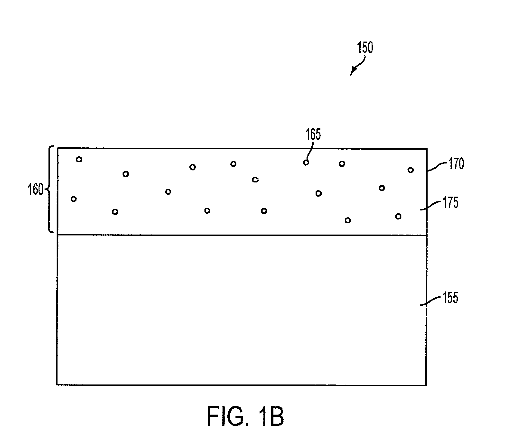
The field breakdown can lead to spot defects known as charge depleted spots (CDS).
If an imaging device has an issue with CDS, the substrate outputs produced by the imaging device can have noticeable spots that reduce the accuracy and quality of the prints.
Because the life counter replacement value of the photoreceptor is affected by a number of customer usage factors, such as, for example, area coverage, environmental conditions, developer age, and job length, the estimated remaining useful life of the photoreceptor may not be accurate.
As a result, the photoreceptor may fail, and CDS defects may occur, before the estimated life limit is reached.
Further, the photoreceptor may have remaining workable cycles when the estimated life limit is reached.

Method used


Image

  • Photoreceptor diagnostic method based on detection of charge deficient spots
  • Photoreceptor diagnostic method based on detection of charge deficient spots
  • Photoreceptor diagnostic method based on detection of charge deficient spots

Examples


Embodiment Construction

[0006]The following presents a simplified summary in order to provide a basic understanding of some aspects of one or more embodiments of the invention. This summary is not an extensive overview, nor is it intended to identify key or critical elements of the invention nor to delineate the scope of the invention. Rather, its primary purpose is merely to present one or more concepts in simplified form as a prelude to the detailed description presented later.

[0007]In accordance with the present teachings, a method of diagnosing a photoreceptor of a device is provided. The method comprises executing a set of cycles of the device, sensing a component associated with the device during each of the set of cycles to establish defect data, and processing the defect data to identify one or more charge deficient spots (CDS) in the defect data. Further, the method comprises determining whether the photoreceptor needs replacement based on the identified one or more CDS.

[0008]In accordance with th...


PUM


Abstract

Systems and methods of diagnosing a photoreceptor associated with an imaging device. The photoreceptor is configured to enter into a diagnostic cycle to complete a set number of cycles. A sensor or array is configured to a scan a component associated with the imaging device during each of the set of cycles to establish defect data. The defect data is analyzed to filter one or more charge deficient spots (CDS) from background noise in the defect data. The systems and methods determine whether the photoreceptor needs replacement based on the determined one or more CDS. The systems and methods are further configured to output a report of the determination. The determination is conducted at fixed or variable intervals throughout the life of the photoreceptor and / or imaging device.

Description

FIELD OF THE INVENTION[0001]This invention relates to the field of printing and imaging devices, and more particularly to systems and methods for diagnosing a photoreceptor based on a detection of charge deficient spots.BACKGROUND OF THE INVENTION[0002]Xerographic or electrophotographic image forming methods and systems are used in marking or imaging devices such as copiers, scanners, fax machines, laser printers, multifunction devices, and the like. A photoreceptor of the imaging devices can have a charge transport layer (CTL) that can carry the charge that determines toner placement on a substrate to be copied or printed. Over the lifecycle of the imaging device and corresponding photoreceptor, the CTL can deplete and reduce in thickness, which can cause the photoreceptor to be more susceptible to field breakdown within the CTL. The field breakdown can lead to spot defects known as charge depleted spots (CDS). If an imaging device has an issue with CDS, the substrate outputs produ...

Claims


Application Information

Patent Timeline
IPC IPC(8): G03G15/00
CPCG03G15/75G03G15/5037
Inventor PAUL, PETERBURRY, AARON MICHAELZONA, MICHAEL F.HAMBY, ERIC S.
Owner XEROX CORP
Learn More