Industrial robot system
- Summary
- Abstract
- Description
- Claims
- Application Information
AI Technical Summary
Benefits of technology
Problems solved by technology
Method used
Image

Examples
example 1
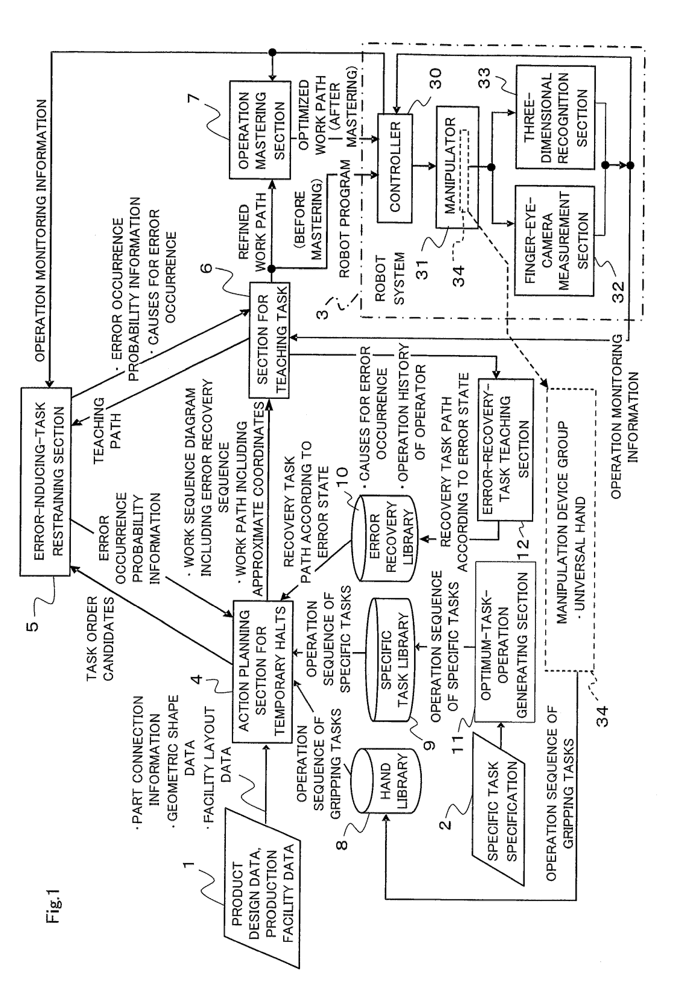
[0045]FIG. 1 is a block configuration diagram illustrating an industrial robot system according to Example 1 of the present invention.
[0046]The industrial robot system in FIG. 1 includes product design data and production facility data 1 (including part connection information, geometric shape data, and facility layout data) produced and prepared in advance by three-dimensional CAD, a specific task specification 2 produced and prepared in advance, and a robot system 3 installed in a production line.
[0047]Moreover, the industrial robot system includes, as components relating to the production design data and production facility data 1, the specific task specification 2, and the robot system 3, an action planning section 4 for temporary halts, an error-inducing-task restraining section 5, a section 6 for teaching task, an operation mastering section 7, a hand library 8, a specific task library 9, an error recovery library 10, an optimum-task-operation generating section 11, an error-re...
example 2
[0311]The general example in which most of the respective functional configuration sections 4 to 12 are implemented as so-called software on a personal computer is described in Example 1 (FIG. 1). However, control devices for production facilities including personal computer OSes, various real time OSes, and no OS are mixed in the real world of the factory automation, and it is thus necessary to use software serving as glue for data exchange, data exchange, data communication, data exchange, and media conversion in a distributed environment of intelligent module software implemented as software on a personal computer such as the RT (robot technology) platform and various control devices. Therefore, mashup sections 51 and 52 may be provided as illustrated in FIG. 20.
[0312]FIG. 20 is an explanatory diagram conceptually illustrating an industrial robot system according to Example 2 of the present invention, and illustrating a positional relationship of the mashup section 51 for realizi...
example 3
[0322]Though an offline teaching section including an error detection function for detecting a task error, and also including the functions of the error-inducing-task restraining section 5 and the hand library 8 may be provided as illustrated in FIGS. 21 to 24, which is not particularly mentioned in Example 1 (FIG. 1).
[0323]The error detection function for detecting a task error and the error restraining function for restraining an error from occurring are effective, and Example 3 of the present invention thus includes the offline teaching section including these functions.
[0324]The offline teaching section includes an error-recovery-level determination function and an error occurrence risk analysis function in addition to the error detection function, the error restraining function, and the hand library function.
[0325]The error detection function of the offline teaching section supports building of a task error detection logic from various types of sensor information (robot positio...
PUM
 Abstract
Description
Claims
Application Information
 - R&D
- Intellectual Property
- Life Sciences
- Materials
- Tech Scout
- Unparalleled Data Quality
- Higher Quality Content
- 60% Fewer Hallucinations
Browse by: Latest US Patents, China's latest patents, Technical Efficacy Thesaurus, Application Domain, Technology Topic, Popular Technical Reports.
© 2025 PatSnap. All rights reserved.Legal|Privacy policy|Modern Slavery Act Transparency Statement|Sitemap|About US| Contact US: help@patsnap.com