Control method of dryer

a control method and dryer technology, applied in drying machines, lighting and heating equipment, furnaces, etc., to achieve the effect of improving the structure of compressors and supplying heated air quickly

Active Publication Date: 2011-12-01
LG ELECTRONICS INC
View PDF18 Cites 21 Cited by
  • Summary
  • Abstract
  • Description
  • Claims
  • Application Information

AI Technical Summary

Benefits of technology

[0007]An object of the present invention is to provide a control method of a dryer which improves a structure of a compressor provided in a heat pump generating heated air, to make it possible to supply the heated air quickly in an initial driving period.

Problems solved by technology

A variety of dryers have been developed and the dryers accompany a variety of problems.

Method used


Image

  • Control method of dryer
  • Control method of dryer
  • Control method of dryer

Examples


Embodiment Construction

[0019]Reference will now be made in detail to the specific embodiments of the present invention, examples of which are illustrated in the accompanying drawings. Wherever possible, the same reference numbers will be used throughout the drawings to refer to the same or like parts.

[0020]As follows, a dryer according to an exemplary embodiment of the present invention will be described in detail in reference to the accompanying drawings.

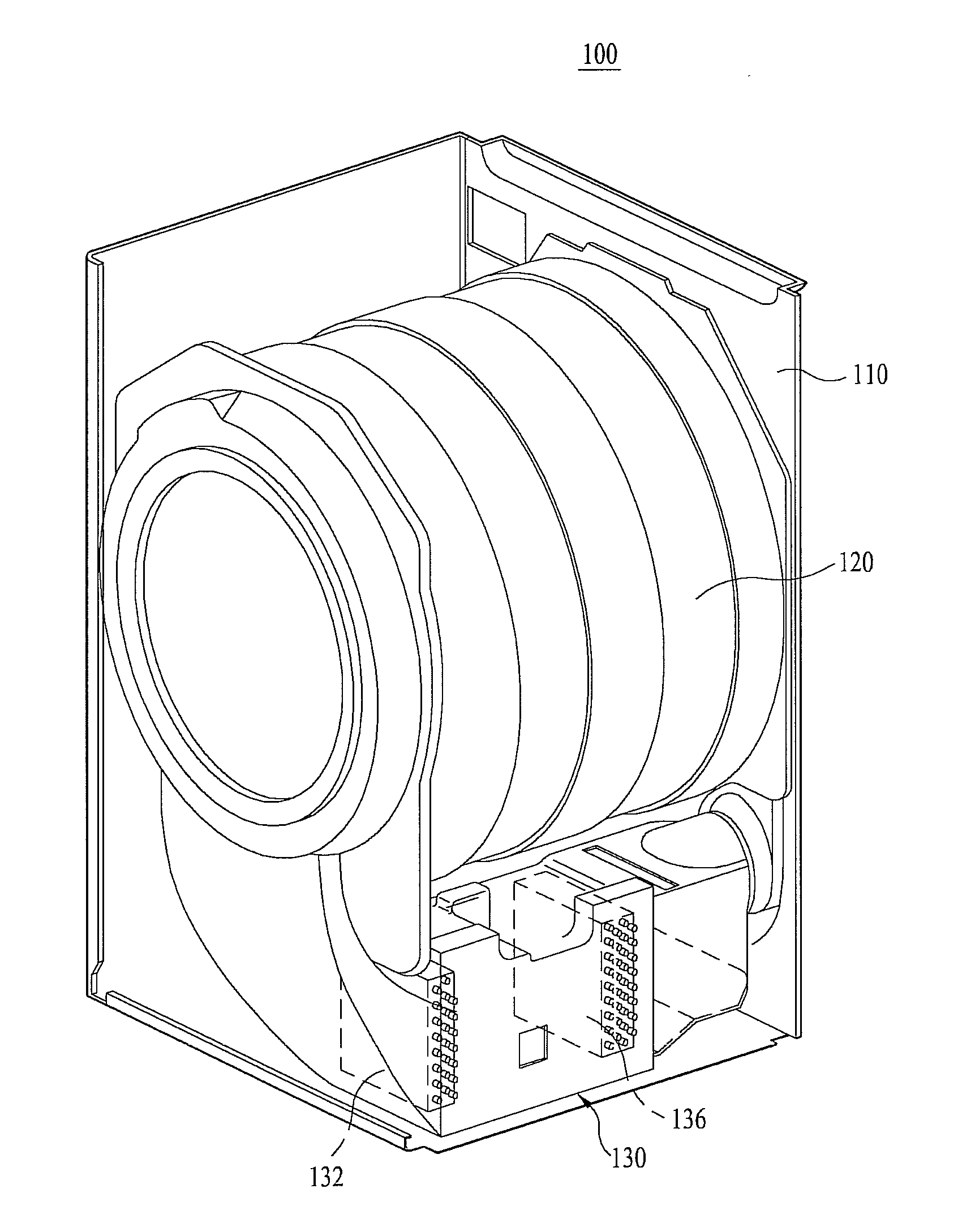
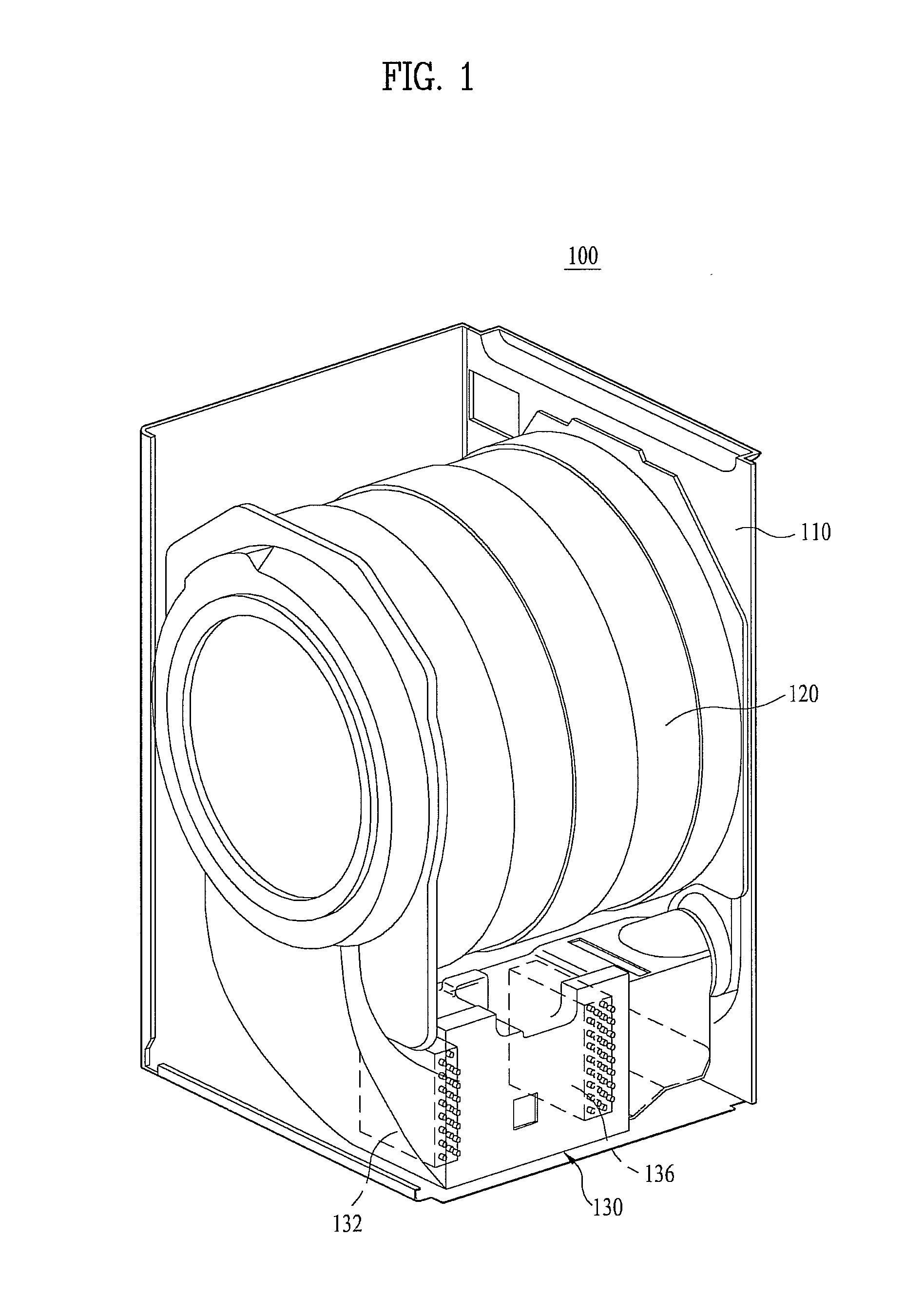
[0021]FIG. 1 is a perspective view illustrating a dryer according to an exemplary embodiment of the present invention.

[0022]In reference to FIG. 1, the dryer 100 according to the embodiment of the present invention includes a cabinet 110 forming an exterior appearance thereof. The dryer 100 further includes a drum 120 which is selectively rotatable within the cabinet 110. Drying objects may be loaded into the drum 120. Although not shown in the drawings, the dryer 100 may include a user operational part (not shown) to receive at least one piece of drying...


PUM


Abstract

A control method of a dryer is disclosed. A control method of a dryer including a heat pump having a inverter compressor includes determining a driving condition of the dryer; and adjusting at least one of an electric power supplied to the inverter compressor and a driving velocity of the compressor based on the driving condition.

Description

CROSS REFERENCE TO RELATED APPLICATION[0001]This application claims the benefit of the Patent Korean Application No. 10-2010-0039367, filed on Apr. 28, 2010, 10-2010-0039373 filed on Apr. 28, 2010 and 10-2010-0041999 filed on May 4, 2010, which are hereby incorporated by reference as if fully set forth herein.BACKGROUND OF THE DISCLOSURE[0002]1. Field of the Disclosure[0003]The present invention relates to a control method of a dryer.[0004]2. Discussion of the Related Art[0005]Laundry devices may be categorized into washing machines, dryers which can perform drying and washing machines having a drying function which can perform washing and drying. Dryers are electric appliances which supply heated dry air to drying objects to dry them. A variety of dryers have been developed and the dryers accompany a variety of problems.SUMMARY OF THE DISCLOSURE[0006]Accordingly, the present invention is directed to a control method of a dryer.[0007]An object of the present invention is to provide ...

Claims


Application Information

Patent Timeline
Patent Type & Authority Applications(United States)
IPC IPC(8): F26B3/02
CPCD06F58/206D06F58/28D06F2058/2803D06F2058/2854Y02B40/72D06F2058/287F26B23/005Y02B30/52D06F2058/2861D06F58/34D06F2101/04D06F2101/18D06F2101/20D06F2103/02D06F2103/50D06F2105/26Y02P70/10Y02B40/00
Inventor NOH, HYUN WOOLEE, YONG JULEE, SANG IK
Owner LG ELECTRONICS INC
Why Eureka
Try Eureka