Vacuum valve

a vacuum valve and valve body technology, applied in the field of vacuum valves, can solve the problems of insufficient heat transfer efficiency, inability to replace the heater, complicated attachment mechanism of the heater, etc., and achieve the effects of convenient attachment and replacement, efficient heating, and high heat transfer efficiency

Active Publication Date: 2011-12-01
SMC CORP
View PDF5 Cites 8 Cited by
  • Summary
  • Abstract
  • Description
  • Claims
  • Application Information

AI Technical Summary

Benefits of technology

[0013]According to the present invention, the outer circumferential surface of the heating portion of the cartridge heater is brought into plane-to-plane contact with the inner circumferential surface of the arcuate heat receiving groove formed on the valve element, so that the valve element is directly heated by heat conduction, and therefore higher heat transfer efficiency can be attained in comparison with heat transfer by radiation, and the valve element can be efficiently heated. Also, the cartridge heater is inserted in the heater bore of the shaft such that the heating portion is located between the heat receiving groove of the valve element and the pressurizing portion of the shaft, and the heating portion is pressed into close contact with the heat receiving groove by the pressurizing portion, by fastening the valve element and the shaft with the bolt, and therefore the cartridge heater can be easily attached and replaced.

Problems solved by technology

Regarding the heating methods disclosed in Patent Literature 1 and Patent Literature 2, however, such a method as providing a heater inside the shaft and a hot plate at the back of the valve element, thereby transmitting the heat of the heater to the valve element through the hot plate, is an indirect heating method with the intermediation of the hot plate, and hence has a drawback that sufficient heat transfer efficiency cannot be attained.
Another method is forming a loop-shaped groove in the back of the valve element along a periphery thereof, and placing a heater in the groove thereby heating the valve element, however the formation of the loop-shaped groove in the valve element is a troublesome work, and besides a seal plate and the hot plate have to be attached to the back of the valve element to tightly seal the groove, and therefore the attachment mechanism of the heater becomes so complicated that the heater cannot be replaced.

Method used


Image

  • Vacuum valve
  • Vacuum valve
  • Vacuum valve

Examples


Embodiment Construction

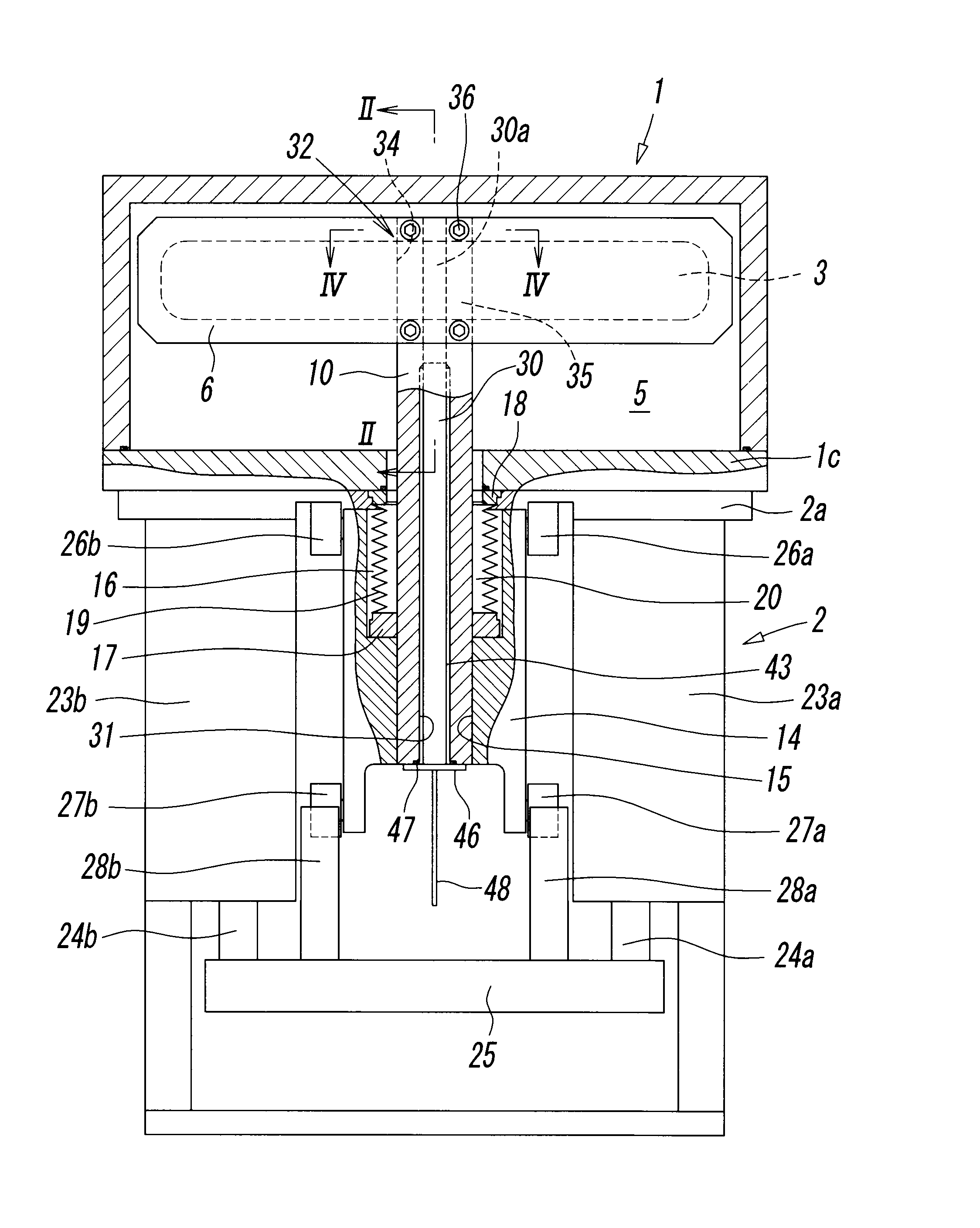
[0021]FIG. 1 is a partially cut away schematic drawing of a vacuum valve according to an embodiment of the present invention. The vacuum valve is to be connected to a vacuum chamber of a semiconductor manufacturing apparatus and is for opening and closing an aperture 3 communicating with the vacuum chamber, upon such occasions as ventilating the vacuum chamber and bringing or taking semiconductor wafers into or out of the vacuum chamber.

[0022]The vacuum valve includes a valve housing 1 to be connected to the vacuum chamber, and a valve element driving unit 2 placed under the valve housing 1.

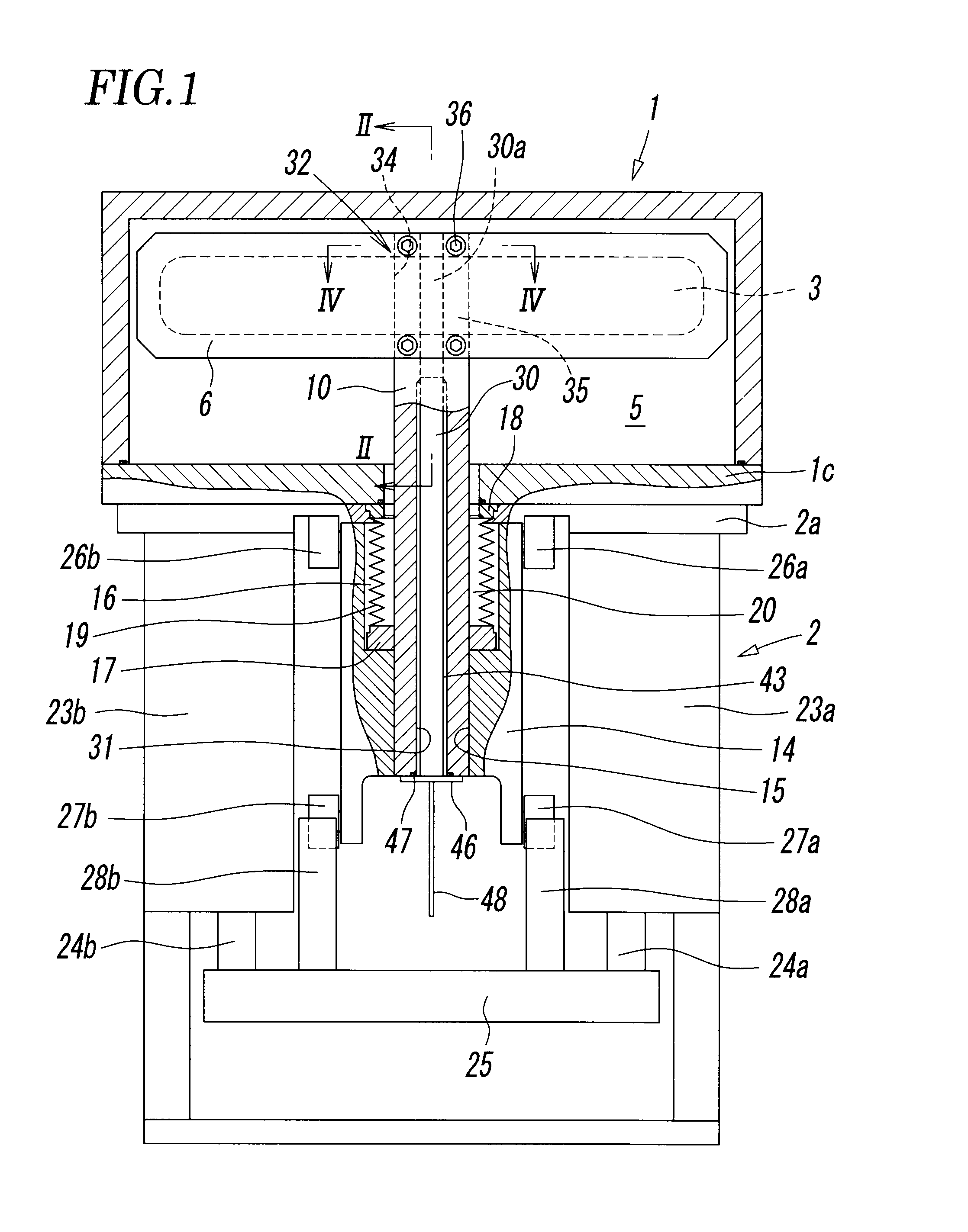
[0023]The valve housing 1 is of a rectangular box shape that is wider than it is tall, and includes a first aperture 3 and a second aperture 4 of a rectangular shape that is wider than it is tall for allowing communication with the vacuum chamber, formed in a front wall 1a and a rear wall 1b opposing each other, as shown in FIG. 2, and a valve element 6 of a rectangular shape that is wider than i...


PUM


Abstract

A cartridge heater is accommodated in a heater bore in a shaft connected to a valve element, and a heating portion provided at an end portion of the cartridge heater is located at a joint portion of the shaft and the valve element. At the joint portion, a heat receiving groove and a pressurizing portion communicating with the heater bore are provided at a position between a surface of the valve element and that of the shaft located so as to oppose and to contact each other. The heat receiving groove includes an arcuate groove portion of the same radius as that of the heating portion of the cartridge heater, and the heating portion is pressed by the pressurizing portion to enter into plane-to-plane contact with an inner circumferential surface of the arcuate groove portion of the heat receiving groove, upon fastening the valve element and the shaft to each other with a bolt, with the heating portion located between the heat receiving groove and the pressurizing portion.

Description

BACKGROUND OF THE INVENTION[0001][1] Field of the Invention[0002]The present invention relates to a vacuum valve to be attached to a vacuum chamber of a semiconductor manufacturing apparatus, for opening and closing an aperture communicating with the vacuum chamber.[0003][2] Description of the Related Art[0004]In semiconductor manufacturing apparatuses, a vacuum valve is employed for opening and closing an aperture communicating with a vacuum chamber. The vacuum valve includes a valve housing having the aperture, a valve element accommodated therein, a shaft having an end portion connected to the valve element, and a valve element driving unit that drives the shaft thereby causing the valve element to open and close the aperture.[0005]In the vacuum valve, substances generated from a reaction are deposited onto a portion exposed to a reaction gas thereby affecting the opening and closing action of the valve element, and hence it is essential to prevent deposition of such substances. ...

Claims


Application Information

Patent Timeline
Patent Type & Authority Applications(United States)
IPC IPC(8): F16K51/02
CPCF16K3/3165F16K51/02F16K49/002Y10T137/6416Y10T137/6606F16K3/16F16K3/18F16K49/00
Inventor ISHIGAKI, TSUNEOOGAWA, HIROSHISHIMODA, HIROMI
Owner SMC CORP
Why Eureka
Try Eureka