Compartmentalized field flow fractionation

a fractionation field and fractionation technology, applied in the direction of filtration separation, separation process, instruments, etc., can solve the problems of inability to detect fractions such as correspondingly very low concentrations, associative limitations, and no longer be subject to the cross force needed to continue separation

Active Publication Date: 2011-12-01
WYATT TECH
View PDF1 Cites 6 Cited by
  • Summary
  • Abstract
  • Description
  • Claims
  • Application Information

AI Technical Summary

Benefits of technology

[0018]The multi-region frit structure, each region of which provides a selectable cross flow into a specific compartment therebelow, is capable of a wide variety of separations heretofore not possible within the traditional A4F and SF1FFF structures. Indeed, the capabilities of CFFF are so broad and extensive that the apparatus and means for their control open up new vistas for the study and application of the FFF process itself. Such a generalized frit structure allows simultaneous separations of complex particle distributions that may be present within a single injected sample.

Problems solved by technology

Although such programming is capable of producing effective separations for a wide variety of particle classes, it has associated limitations.
Upon leaving the channel, subsequent analyses using various detection means may be unable to detect fractions of such correspondingly very low concentration.
While the retained larger particles as yet may not have had sufficient time to complete their passage through the channel and to separate therein, the smaller particles may have long left the channel and no longer, therefore, be subject to the cross forces needed to continue their separation.
Optimal fractionation of one group of sizes does not insure an equivalent or even comparable fractionation of another group of sizes.
A continuing problem for such FFF separations lies in the historic inability of these techniques to vary local flow conditions within the channel.
There are other difficulties with the A4F fractionator despite its superficial simplicity.
First, there is a common problem to both SF1FFF and A4F: the four surfaces that define the channel are of different materials and one of them may depart from the expected laminar flow patterns of the theory.
For both A4F and SF1FFF flow, however, conditions at the membrane boundary are not well understood.

Method used


Image

  • Compartmentalized field flow fractionation
  • Compartmentalized field flow fractionation
  • Compartmentalized field flow fractionation

Examples


Embodiment Construction

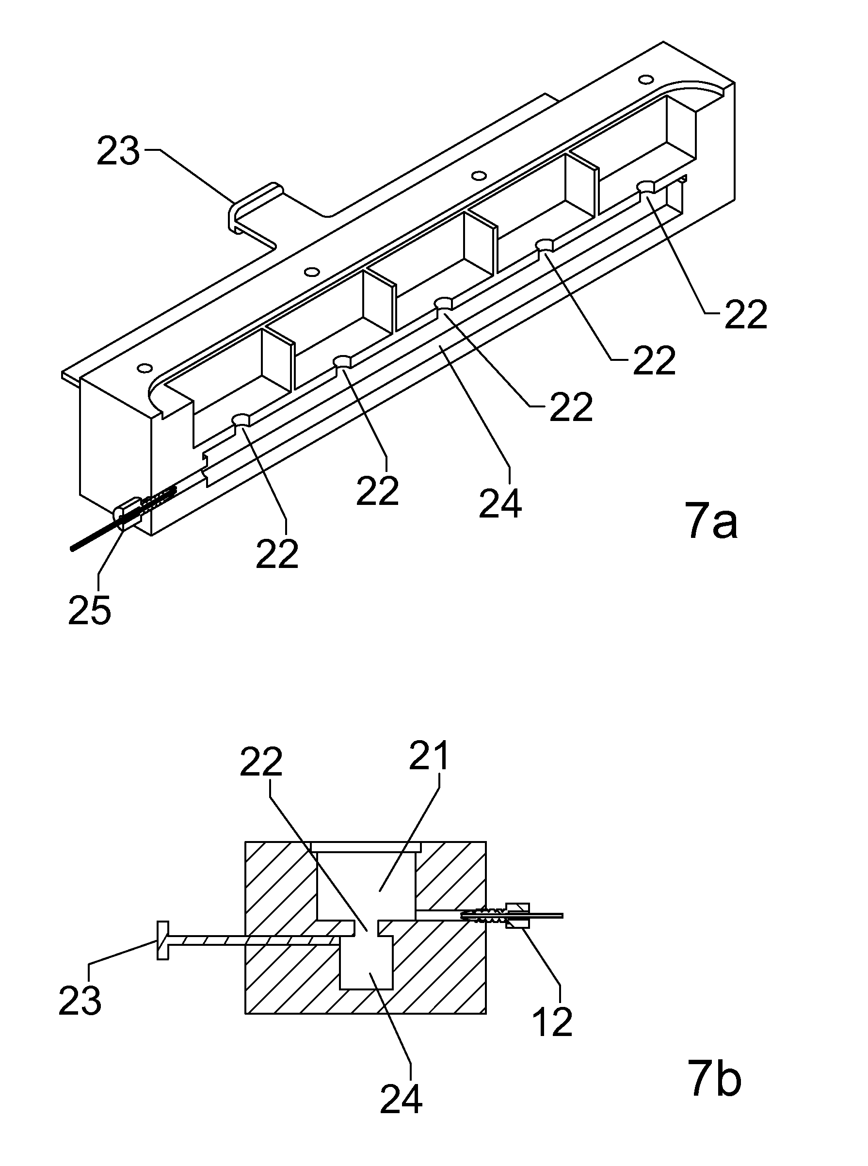
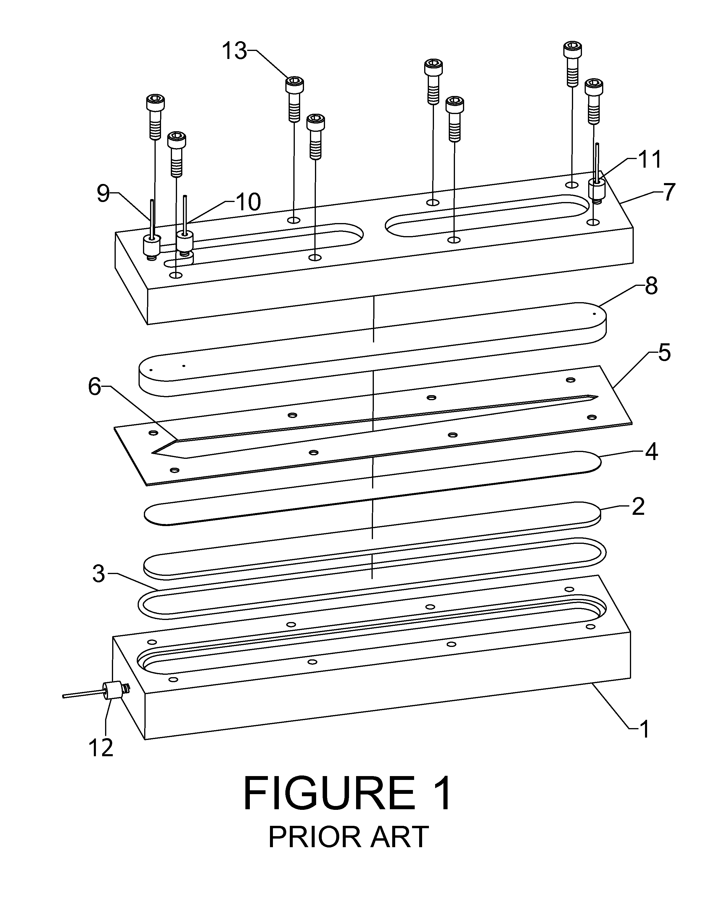
[0031]We begin with a review of the elements of an asymmetric flow FFF channel. The A4F channel, illustrated in FIG. 1, is comprised of the following elements together with means to hold them together:[0032]1) a bottom assembly structure 1 holding a liquid-permeable frit 2 surrounded by a sealing O-ring 3,[0033]2) a permeable membrane 4 that lies on the frit 2,[0034]3) a spacer 5 of thickness from about 75 μm to 800 μm into which has been cut a cavity 6, and[0035]4) a top assembly structure 7 generally holding a transparent plate 8 of material such as Lexan® or glass. The plate need not be transparent for some implementations.

[0036]The resulting sandwich is held together with bolts 13 or other means. The generally coffin-shaped or tapered cavity 6 in the spacer 5 will serve as the channel in which separation will occur. The top assembly structure 7 usually contains three holes, called ports, that pass through the top plate 8 and are centered above the channel permitting the attachme...


PUM

PropertyMeasurementUnit
sizeaaaaaaaaaa
sizeaaaaaaaaaa
permeableaaaaaaaaaa

Abstract

A field flow fractionator to separate particles contained within an injected sample aliquot is described. As required, said fractionator may be used to capture, for subsequent removal, specific predefined classes of such particles. Based upon the cross flow or asymmetric flow field flow fractionators, the fractionator disclosed contains means to vary the applied transverse flows at a plurality of locations along the length of its separating channel. A plurality of separated compartments, each lying below a distinct and corresponding membrane supporting permeable frit segment, are provided individual means to control the localized flow through the membrane section thereabove. A corresponding concentric compartment implementation achieves the same type of compartmentalized cross flow when integrated with a hollow fiber fractionator.

Description

RELATED APPLICATIONS AND PATENTS[0001]The following patents and applications relate to similar characterizations of separated molecules and small particles:U.S. Pat. No. 6,774,994, P. J. Wyatt and M. Weida “Method and apparatus for determining absolute number densities of particles in suspension” 10 Aug. 2004.P. J. Wyatt, M. H. Chen, and D. N. Villalpando “Method and apparatus for optimizing the separation of small particles using Asymmetric Flow Field Flow Fractionation,” Ser. No. 12 / 157,367, filed 9 Jun. 2008.BACKGROUND[0002]Throughout this specification, the term “particle” refers to the constituents of liquid sample aliquots that may be molecules of varying types and sizes, nanoparticles, virus like particles, liposomes, emulsions, bacteria, colloids, etc. Their size range may lie between 1 nm and several thousand micrometers.[0003]The separation of particles in a solution by means of field flow fractionation, FFF, was studied and developed extensively by J. C. Giddings beginnin...

Claims


Application Information

Patent Timeline
Patent Type & Authority Applications(United States)
IPC IPC(8): B01D61/22B01D61/14
CPCG01N2030/007G01N30/0005
Inventor WYATT, PHILIP J.
Owner WYATT TECH
Why Eureka
Try Eureka