Electromechanical device

Inactive Publication Date: 2011-12-01
GK BRIDGE 1
View PDF4 Cites 2 Cited by
  • Summary
  • Abstract
  • Description
  • Claims
  • Application Information

AI Technical Summary

Benefits of technology

[0006]An advantage of some aspects of the invention i

Problems solved by technology

Particularly, when the motor is used in a moving machine such as a vehicle, a high voltage is applied to the magnet coil to rotationally drive the motor in a high-speed area, thereby increasing the power consumption

Method used


Image

  • Electromechanical device
  • Electromechanical device
  • Electromechanical device

Examples


Example

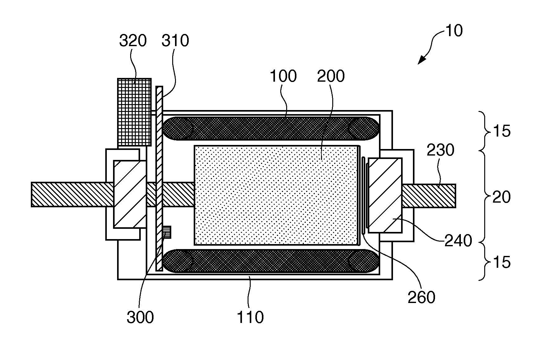
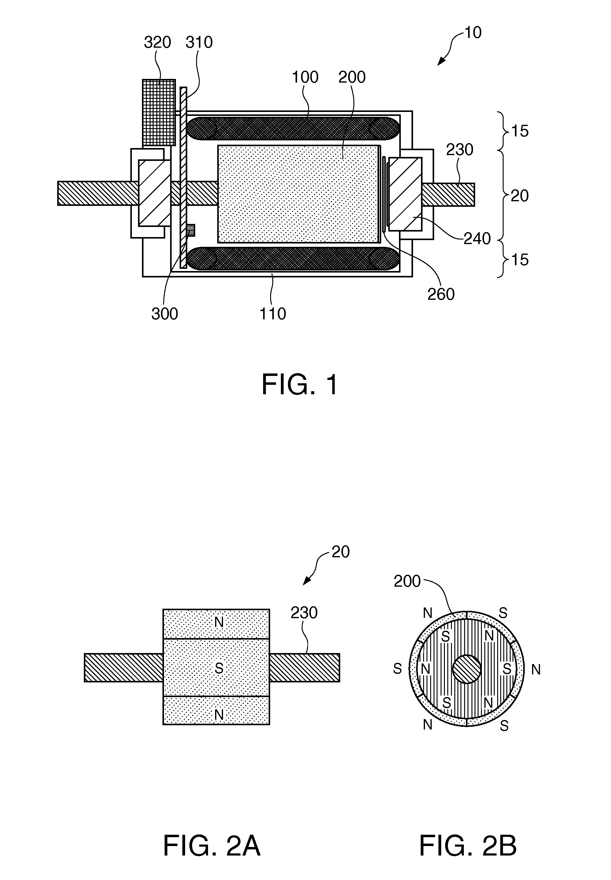
[0046]FIG. 1 is a diagram illustrating a motor according to a first embodiment of the invention. A motor 10 is an inner-rotor motor with a radial gap structure in which a stator 15 having a substantially cylindrical shape is disposed in the outside and a rotor 20 having a substantially cylindrical shape is disposed in the inside. The stator 15 includes plural magnet coils 100 arranged along the inner circumference of a casing 110. The stator 15 further includes magnetic sensor 300 as a position sensor detecting a phase of the rotor 20. The magnetic sensor 300 is fixed to a circuit board 310 and the circuit board 310 is fixed to the casing 110. The circuit board 310 is connected to an external control circuit via a connector 320.

[0047]The rotor 20 includes a rotating shaft 230 at the center thereof and includes a permanent magnet 200 on the outer circumference thereof. The rotating shaft 230 is supported by a bearing 240 of the casing 110. The bearing 240 is formed of a non-conductiv...

Example

[0096]FIG. 28 is a diagram illustrating a second embodiment of the invention. In the second embodiment, a regeneration control from the motor 10 (not shown) is performed. In the second embodiment, the control circuit block includes a regeneration controller 700, a U-phase charging switch 710u to a W-phase charging switch 710w, and a secondary battery unit 800. The regeneration controller 700 includes a U-phase regeneration control circuit 700u, a V-phase regeneration control circuit 700v, and a W-phase regeneration control circuit 700w. The configurations of the U-phase regeneration control circuit 700u, the V-phase regeneration control circuit 700v, and the W-phase regeneration control circuit 700w are the same and thus the U-phase regeneration control circuit 700u will be representatively described. The U-phase regeneration control circuit 700u is connected in parallel to the U-phase driving circuit 690u with respect to the U-phase magnet coil 100u. The U-phase regeneration contro...


PUM


Abstract

An electromechanical device includes: a magnet coil; a PWM driving circuit; and a control unit, wherein the control unit performs a first control of setting an excitation interval which is an interval in which a PWM drive signal is supplied to the magnet coil and a second control of changing a duty ratio of the PWM drive signal, and wherein the control unit performs an advance angle control of putting the phase of the center of the excitation interval earlier than the phase in which a counter-electromotive force generated in the magnet coil has the maximum value in the first control, and increases the duty ratio of the PWM drive signal in the second control so that a gain is greater than 100% when the gain is 100% at the time of generating the PWM drive signal so as to have a sinusoidal shape.

Description

BACKGROUND[0001]1. Technical Field[0002]The present invention relates to a technique of controlling an electromechanical device such as a motor or a power generator.[0003]2. Related Art[0004]For example, a motor described in JP-A-2001-298982 has been known.[0005]In the motor, when a voltage applied to a magnet coil is lowered, a rotation speed-torque line moves to a low torque and a low rotation speed. That is, the rotation speed and the output torque are lowered. Accordingly, in order to rotationally drive the motor with a high torque or a high rotation speed, the voltage applied to the magnet coil has to be kept high. Particularly, when the motor is used in a moving machine such as a vehicle, a high voltage is applied to the magnet coil to rotationally drive the motor in a high-speed area, thereby increasing the power consumption of the motor. When the motor is used in a moving machine and is used as a regeneration brake at the time of reducing the speed, the moving machine may be...

Claims


Application Information

Patent Timeline
IPC IPC(8): H02P6/08H02P6/06H02P6/15
CPCH02P27/08B60L7/16B60L15/08B60L2200/26H02P6/24Y02T10/644H02P6/145H02P6/153Y02T10/64
Inventor TAKEUCHI, KESATOSHI
Owner GK BRIDGE 1
Why Eureka
Try Eureka