Method and Apparatus for a Pulsed Coherent Laser Range Finder

a laser range finder and coherent technology, applied in the direction of distance measurement, instruments, using reradiation, etc., can solve the problems of complex apparatus, complex apparatus, and delicate requirements for synchronization between emitted and received pulses, and achieve the effect of high accuracy

Inactive Publication Date: 2011-12-01
RD2 LLC
View PDF5 Cites 40 Cited by
  • Summary
  • Abstract
  • Description
  • Claims
  • Application Information

AI Technical Summary

Benefits of technology

[0008]Therefore, what is needed is a system and method to measure distances, velocities, etc., for example to substantially simultaneously measuring distance and velocity, with high accuracy at close and long ranges usi

Problems solved by technology

Time of flight systems are suitable for measuring longer distances but require complex apparatus and delicate requirements for synchronization between emitted and received pulses.
A number of techniques exist for determining velocities based on measuring Doppler shifts but are not suitable for measuring dista

Method used


Image

  • Method and Apparatus for a Pulsed Coherent Laser Range Finder
  • Method and Apparatus for a Pulsed Coherent Laser Range Finder
  • Method and Apparatus for a Pulsed Coherent Laser Range Finder

Examples


Embodiment Construction

[0024]The present invention is directed to a method and apparatus for a pulsed coherent laser range finder. This specification discloses one or more embodiments that incorporate the features of this invention. The disclosed embodiment(s) merely exemplify the invention. The scope of the invention is not limited to the disclosed embodiment(s). The invention is defined by the claims appended hereto.

[0025]The embodiment(s) described, and references in the specification to “one embodiment,”“an embodiment,”“an example embodiment,” etc., indicate that the embodiment(s) described may include a particular feature, structure, or characteristic, but every embodiment may not necessarily include the particular feature, structure, or characteristic. Moreover, such phrases are not necessarily referring to the same embodiment. Further, when a particular feature, structure, or characteristic is described in connection with an embodiment, it is understood that it is within the knowledge of one skille...


PUM


Abstract

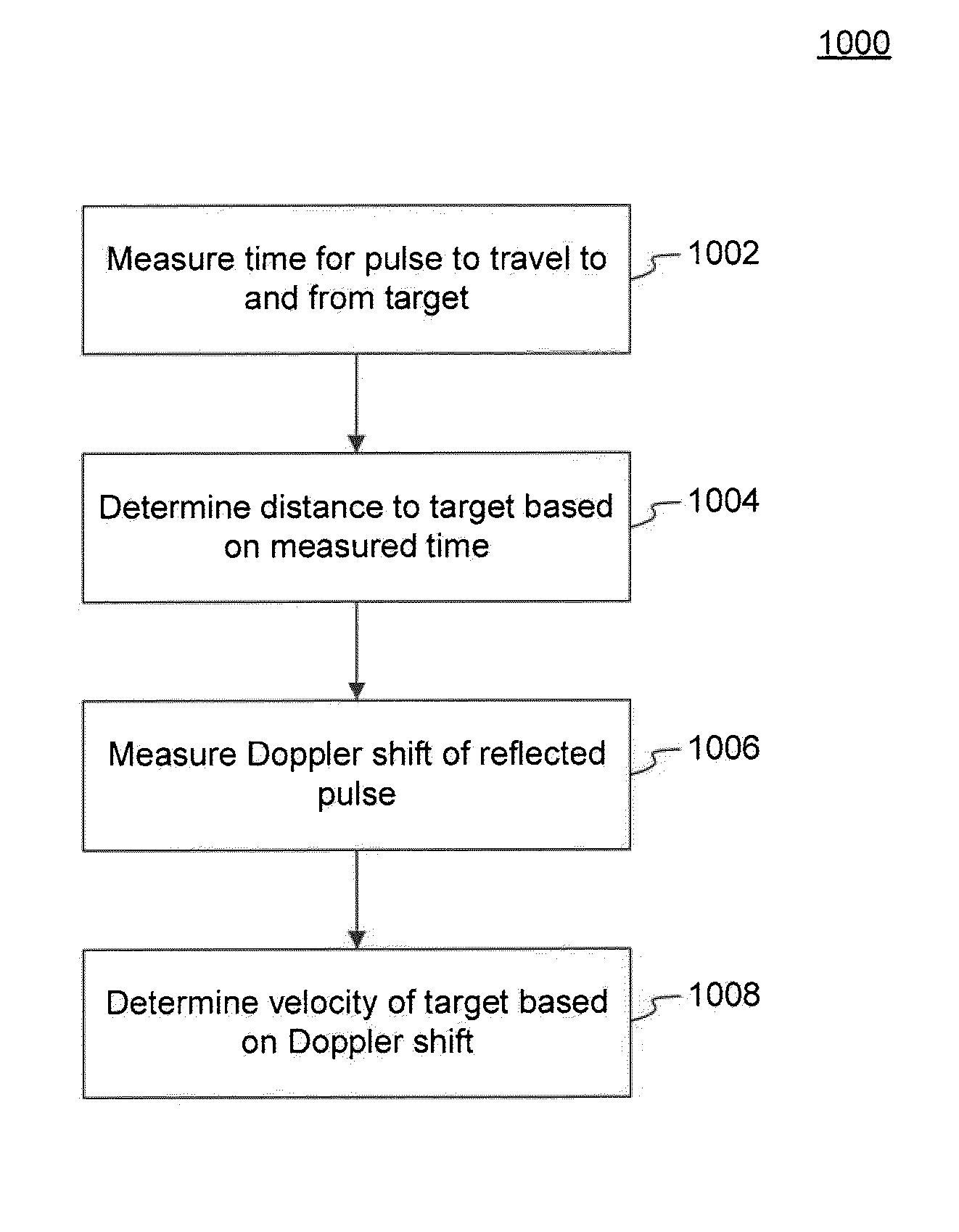
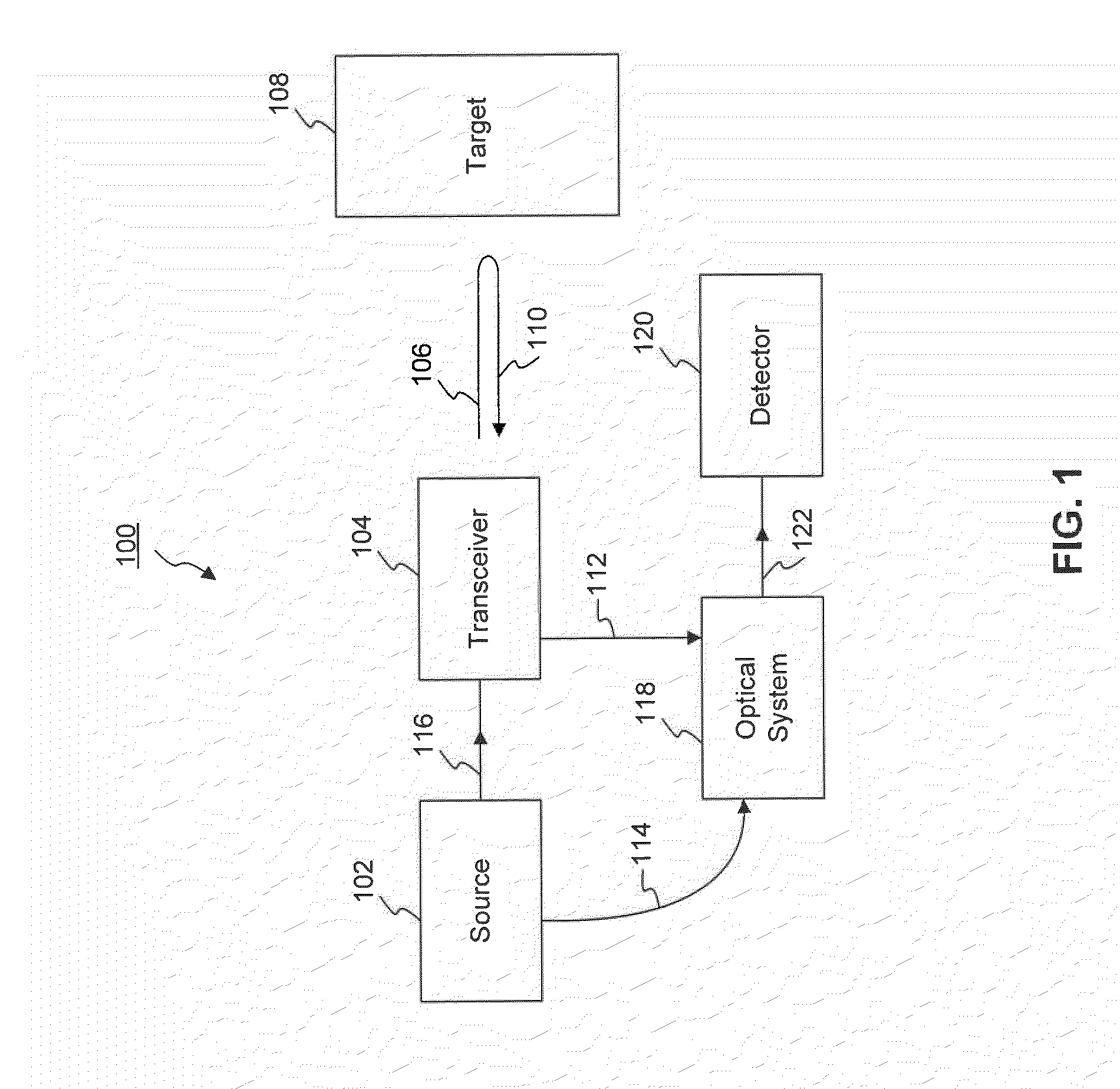
Systems and methods are disclosed for measuring a distance, a velocity, etc., of a target using coherent laser radiation. In one example, a method is provided comprising measuring a time required for a light pulse to travel to and from a target, the light pulse reflecting from the target, and determining the distance to the target based on the measuring. The method also comprises measuring a Doppler shift of the reflected light pulse using an optical detection technique and determining the velocity of the target from the Doppler shift. In a further example, a system is disclosed comprising a transceiver, a coherent source, an optical system and a detector configured to measure the distance to the target based on a measured time for a light pulse to travel to and from the target. The system is also configured to determine the velocity of the target from a measured Doppler shift.

Description

CROSS REFERENCE TO RELATED APPLICATIONS[0001]The present application claims benefit under 35 U.S.C §119(e) to U.S. Provisional Patent Application No. 61 / 349,407 filed May 28, 2010, which is incorporated by reference herein in its entirety.BACKGROUND[0002]1. Field of the Invention[0003]This disclosure relates to systems and methods for measuring the distance, velocity, or the like of an object at long or short ranges using optical coherence detection.[0004]2. Background Art[0005]LIDAR (light detection and ranging) is a technique to measure displacement, range or velocity of a target. Among LIDAR techniques, a laser range finder (LRF) can be used for distance metrology. Various existing techniques can be categorized in terms of three operation principles: interferometry, triangulation and time-of-flight (TOF).[0006]The various techniques have complementary attributes in terms of their ability to measure distances and velocities at short and long ranges. With interferometric schemes, f...

Claims


Application Information

Patent Timeline
IPC IPC(8): G01C3/08G01P3/36G01S17/10G01S7/486
CPCG01S7/4818G01S17/58G01S17/10G01S7/486
Inventor CHANG, CHIA CHEN
Owner RD2 LLC
Why Eureka
Try Eureka