
Wavelength selective switch

a selective switch and wavelength technology, applied in the field of wavelength selective switches, can solve the problems of increasing the necessary cost of an overall apparatus, increasing the weight of the overall apparatus, and increasing the overall size of the overall apparatus

Active Publication Date: 2011-12-01
LUMENTUM OPERATIONS LLC
View PDF9 Cites 17 Cited by
  • Summary
  • Abstract
  • Description
  • Claims
  • Application Information

AI Technical Summary

Problems solved by technology

Moreover, assembly man-hours for that many numbers of members is necessary, thereby leading to an increase in a necessary cost of an overall apparatus.
Moreover, in addition to the increased cost, when the apparatus is structured in multiple stages, an overall size of the apparatus becomes large, and there is an increase in weight of the apparatus.

Method used


Image

  • Wavelength selective switch
  • Wavelength selective switch
  • Wavelength selective switch

Examples


first embodiment

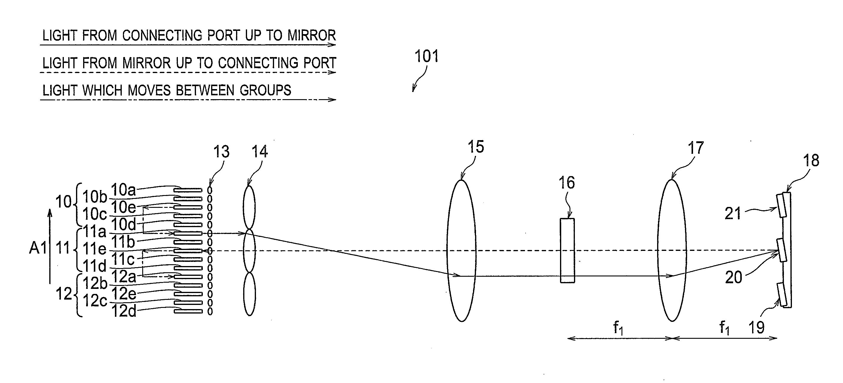
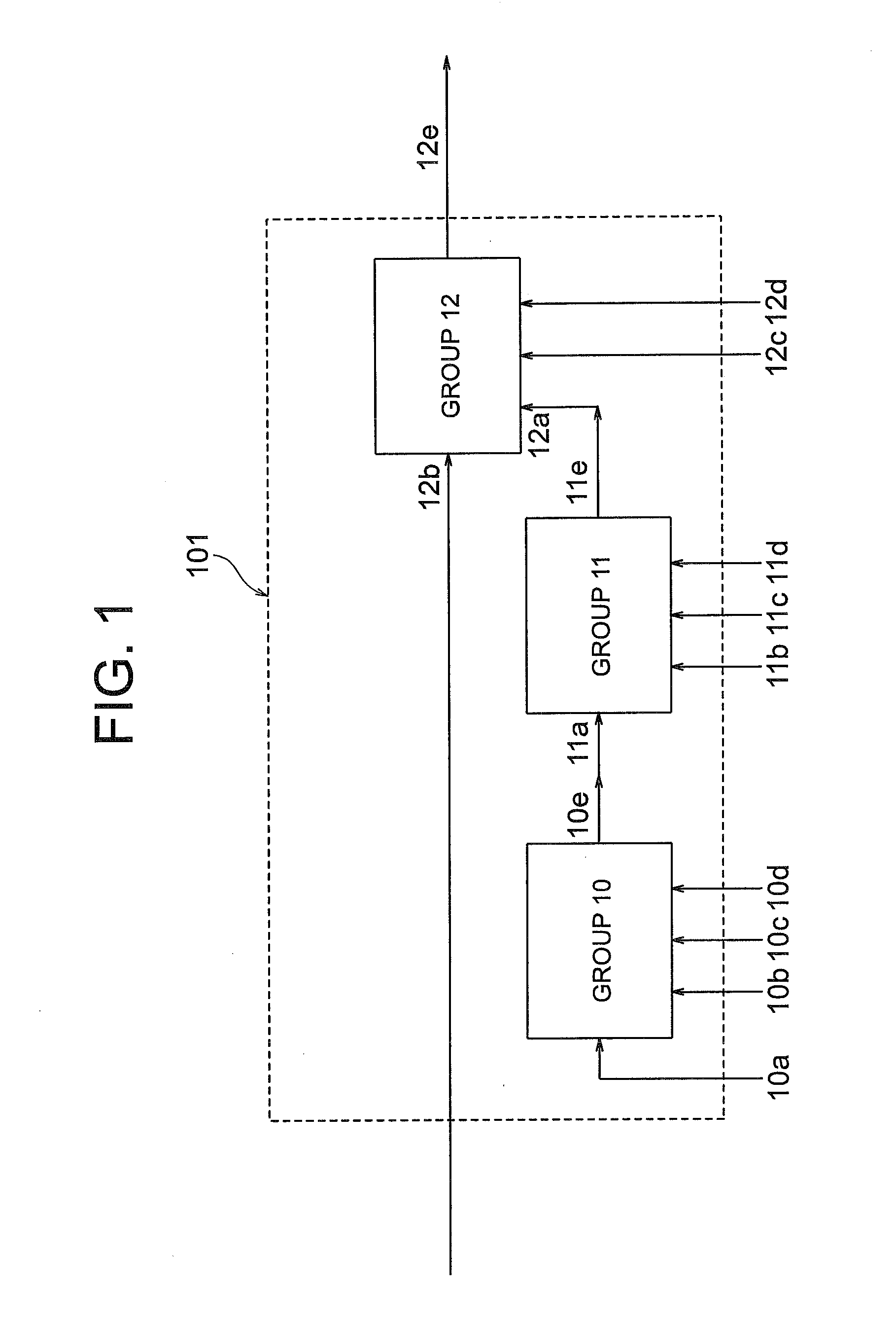
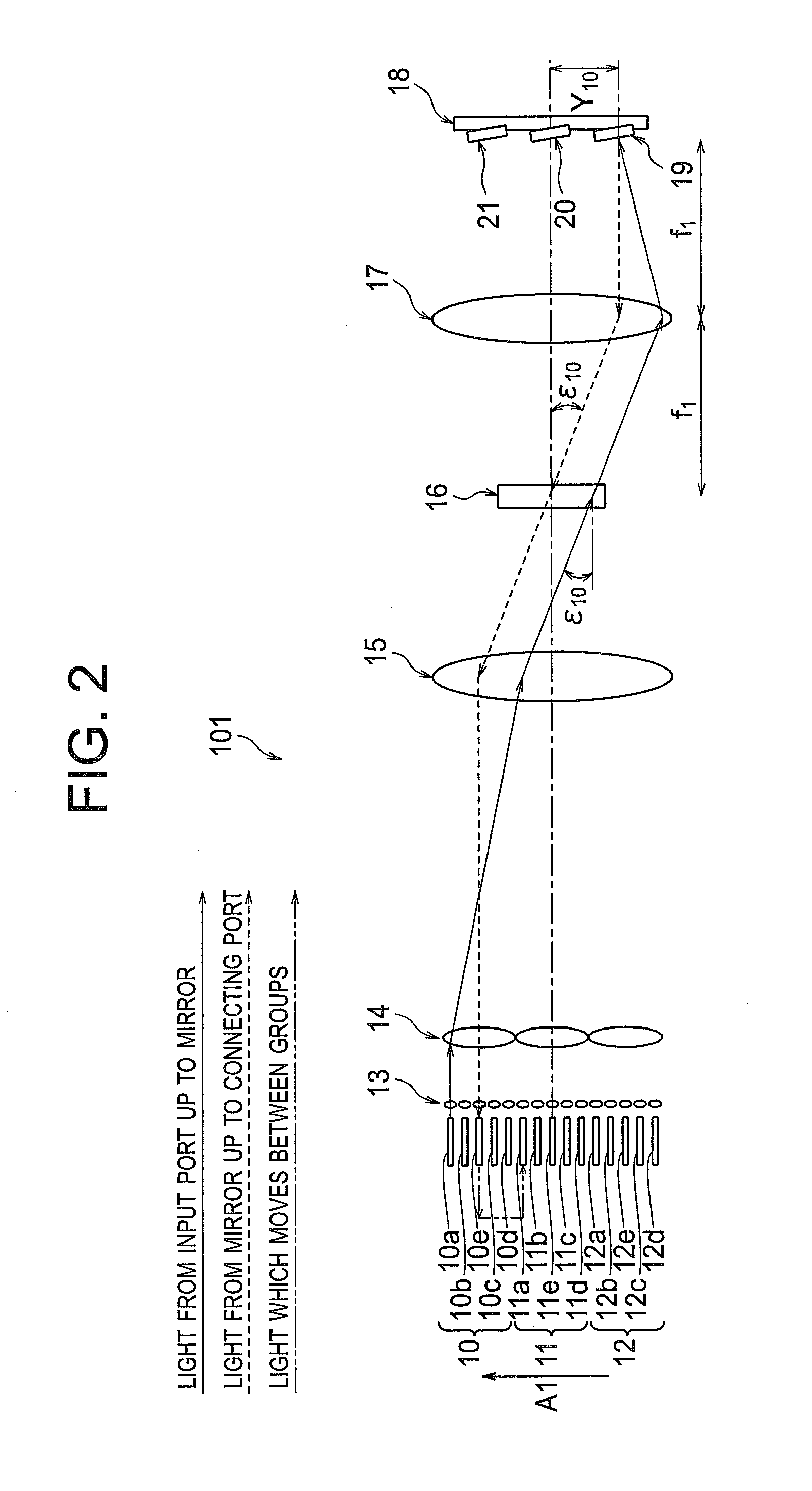
[0071]FIG. 1 is a block diagram showing a concept of a wavelength selective switch 101 according to a first embodiment of the present invention. The wavelength selective switch 101 includes 10 input ports 10a, 10b, 10c, 10d, 11b, 11c, 11d, 12b, 12c, and 12d, and an output port 12e. At an interior of the wavelength selective switch 101, a connecting port 10e of a group 10 and a connecting port 11a of a group 11 are connected mutually, and a connecting port 11e of the group 11 and a connecting port 12a of a group 12 are connected mutually. The groups 10, 11, and 12 form an input output portion.

[0072]In FIG. 1, the 10 input ports and the output port indicate one N×1 wavelength selective switch (N=10). However, an alignment and the number of the input ports, the output ports, and the connecting ports is not restricted to an alignment and the number of ports in FIG. 1.

[0073]An example in which, light which has been input from the input port 10a is output to the output port 12e, will be d...

second embodiment

[0130]For a wavelength selective switch 102 according to a second embodiment of the present invention, in the arrangement of the wavelength selective switch 101 according to the first embodiment shown in diagrams from FIG. 1 to FIG. 12, |ε10| is let to be |ε12| (|ε10|=|ε12|), and ε10 is selected such that X11a . . . , X10b . . . , and X12b are same mutually. The rest of the arrangement is same as in the wavelength selective switch 101 according to the first embodiment. Same reference numerals are assigned to members which are same as in the first embodiment, and the description in detail of such members is omitted.

[0131]Here, FIG. 13 is a side view showing a structure of the wavelength selective switch 102. FIG. 14 is a top view showing the structure of the wavelength selective switch 102. FIG. 15 is a diagram in which, the dispersive element 16 and the second lens 17 are shown in an enlarged form. FIG. 13 shows a path of light since the light is input from the input port 10a till t...

third embodiment

[0139]FIG. 17 is a top view showing a structure of a wavelength selective switch 103 according to a third embodiment of the present invention.

[0140]The wavelength selective switch 103 is an application example when a reflecting lens 25 is used instead of the first lens 15 and the second lens 17 of the wavelength selective switch 101 according to the first embodiment shown in diagrams from FIG. 1 to FIG. 12. Moreover, a reflection dispersive element 26 is used instead of the dispersive element 16 of the first embodiment. The rest of the structure is similar to the structure of the wavelength selective switch 101 according to the first embodiment, and same reference numerals are used for members which are same as in the first embodiment.

[0141]In the wavelength selective switch 103 according to the third embodiment, for simplifying the description, the reflecting lens 25 has been used in common for the first lens 15 and the second lens 17. However, the use of the reflecting lens 25 is ...


PUM


Abstract

A wavelength selective switch includes a light input output portion having an input port and an output port for a wavelength-multiplexed light, which are arranged in an array form in a first direction, a light dispersive unit which separates the wavelength-multiplexed light which has been input from the input port, into respective signal wavelengths, a condenser element which condenses light which has been separated into the signal wavelengths, and a light deflective element array which deflects the signal light in the first direction such that, respective signal wavelength light which has been condensed by the condenser element is switched to a desired output port. In such wavelength selective switch, when m is let to be an integer, the light input output portion is divided into m number of groups, and the light deflective element array is arranged in m number of rows in the first direction to correspond with the m number of groups of the light input output portion, and the light dispersive unit is in common for the m number of groups of the light input output portion.

Description

CROSS-REFERENCE TO RELATED APPLICATION[0001]The present application is based upon and claims the benefit of priority from the prior Japanese Patent Application No. 2010-119532 filed on May 25, 2010; the entire contents of which are incorporated herein by reference.BACKGROUND OF THE INVENTION[0002]1. Field of the Invention[0003]The present invention relates to a wavelength selective switch.[0004]2. Description of the Related Art[0005]As an example of a conventional N×1 wavelength selective switch, a wavelength selective switch 500 of 5×1 used in FIG. 35 and FIG. 36 is available. FIG. 35 is a side view showing a structure of the conventional wavelength selective switch 500, and FIG. 36 is a top view showing the structure of the conventional wavelength selective switch 500. In this case, N is an integer greater than 1.[0006]The wavelength selective switch 500 includes input ports 510a, 510b, 510c, and 510d (hereinafter, ‘input ports 501a to 501d’), an output port 510e, a lens array 530...

Claims


Application Information

Patent Timeline
Patent Type & Authority Applications(United States)
IPC IPC(8): G02B26/08
CPCG02B6/3512G02B6/3558G02B6/356G02B6/3542H04J14/0212H04J14/0213H04J14/0219G02B26/0833
Inventor MATSUMOTO, KOJI
Owner LUMENTUM OPERATIONS LLC
Learn More