Optical inspection device, electromagnetic wave detection method, electromagnetic wave detection device, organism observation method, microscope, endoscope, and optical tomographic image generation device

a technology of electromagnetic wave detection and optical inspection device, which is applied in the direction of optical radiation measurement, diagnostics using spectroscopy, spectral modifiers, etc., can solve the problems of difficult to obtain clear images, low conversion efficiency of excitation light to signal light, and significant weak optical signals obtained from organisms. , to achieve the effect of improving the intensity of light, low cost and high sensitivity

Active Publication Date: 2010-08-19
OLYMPUS CORP
View PDF13 Cites 75 Cited by
  • Summary
  • Abstract
  • Description
  • Claims
  • Application Information

AI Technical Summary

Benefits of technology

[0110]According to the invention, signal light obtained from an object to be inspected is amplified by a light amplification means and then photoelectrically converted by a photodetection means, which makes it possible to photoelectrically convert signal light from the object to be inspected with high sensitivity and promptly with its inexpensive configuration without increasing the intensity of light with which the object to be inspected is irradiated and without using an expensive low-noise and high-sensitivity photodetector as the photodetection means.

Problems solved by technology

Particularly in the imaging method using nonlinear optical effects such as the multiphoton fluorescent imaging, the CARS imaging or the like, the conversion efficiency from excitation light to signal light is essentially low, and thus the optical signals obtained from an organism are significantly weak.
Therefore, it is difficult to obtain a clear image.
However, when an organism is irradiated with light having excessively high intensity, it could be possible to damage the organism.
Therefore, it is difficult to obtain a clear image in lots of cases.
However, the low-noise and high-sensitivity photodetector is of particular and very expensive.
Moreover, in the above conventional photodetection technique using signal amplification in an electric domain, the volume of noises generated from a photodetector and accumulated time of signal light by the photodetector have the inverse relationship, that is, the trade-off relationship therebetween, which requires sufficiently long accumulated time to obtain low-noise detection signals.
As a result, sufficiently long accumulated time is needed to obtain a clear image after detecting weak signal light, thus extending time for obtaining an image.
Therefore, real-time properties lack for needs to properly observe an organism varying with time, and it could be possible to inhibit basic needs by optical imaging users.
Therefore, it is unavoidable in the present situation that either of detection speed or detection sensitivity is sacrificed to perform photodetection.
It is noted that such problem occurs not only in optical imaging methods but also in optical measuring methods such as the flow site meter optically analyzing fine particles in fluid, the fluorescence correlation spectroscopy (FCS) optically analyzing motion of fluorescently-labeled biomolecules in solution, the surface plasmon resonance method (SPR) optically analyzing the state of connection among biologically-relevant molecules fixed on the surface of a solid substrate and the latex photometric immunoassay (LPIA) optically analyzing the state of connection among biologically-relevant molecules in solution and the fluoroimmunoassay (FIA) detecting immune response in solution based on the existence or nonexistence of fluorescent label.
Moreover, Amplified spontaneous emission (ASE) is generated from the optical amplifier, which is a dominant cause of noises in photodetection using the optical amplifier.
However, even such a low-noise optical amplifier for long-distance optical communication constituted by a single-mode optical fiber has the following problem when used before a photoelectric conversion device.
Such light has significantly low coupling efficiency to a single-mode optical fiber, and the light signal which can be taken in the optical amplifier is weak signals being of limited one portion of the whole.
Therefore, the SNR is deteriorated and thus the high light-receiving sensitivity cannot be obtained.
However, since optical noises generated in the optical amplifier increase in accordance with the increase of the number of spatial modes resulted by increasing the core diameter, the SNR deteriorates in this case also and thus the high light-receiving sensitivity cannot be obtained.
Although the above is described with an example of a case in which light is detected, it is conceivable that cases in which electromagnetic waves other than light such as millimeter waves, microwaves and the like are detected also have the same problem.
However, the penetration depth of tomographic images obtained by OCT is presently about only 1 to 2 mm, and thus the performance is insufficient in diagnosis of penetration of cancer which is essential for early detection thereof.
Thus, the applied range is limited.
Particularly in the case of SSOCT, quantization noises (quantization errors) in an analog-digital converter (ADC) are the cause of limiting the penetration depth.

Method used


Image

  • Optical inspection device, electromagnetic wave detection method, electromagnetic wave detection device, organism observation method, microscope, endoscope, and optical tomographic image generation device
  • Optical inspection device, electromagnetic wave detection method, electromagnetic wave detection device, organism observation method, microscope, endoscope, and optical tomographic image generation device
  • Optical inspection device, electromagnetic wave detection method, electromagnetic wave detection device, organism observation method, microscope, endoscope, and optical tomographic image generation device

Examples


first embodiment

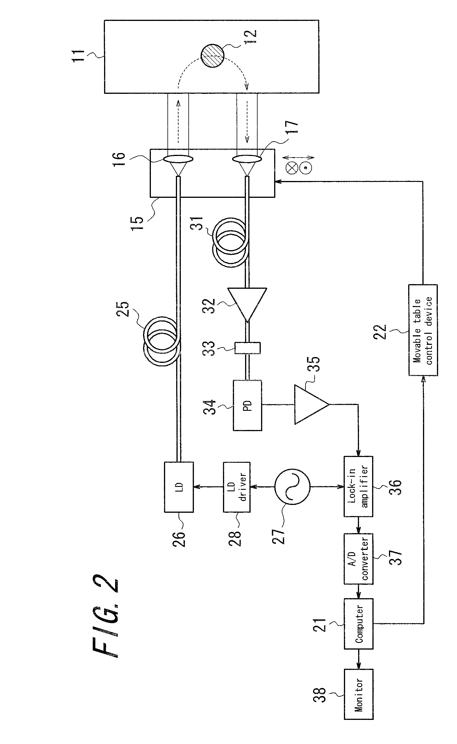
[0297]FIG. 2 is a functional block diagram illustrating a configuration of the optical inspection device according to the first embodiment of the invention. The optical inspection device is a device for visualizing a route condition of a blood vessel 12 buried in fat 11 when a rigid endoscope is inserted to the inside of a body to approach organs like a stomach covered by fat. The device enables the scope-assisted surgery with avoiding bleeding due to wrong cutting of the blood vessel 12.

[0298]For this reason, the optical inspection device shown in FIG. 2 is provided, at a distal insertion portion of a rigid endoscope which is not shown, with a movable table 15 which can be moved in two-dimensional direction in a plane perpendicular to an insertion direction, and the movable table 15 is provided with a projector lens 16 for irradiating the object to be inspected with light and a collective lens 17 for collecting signal light from the object to be inspected at intervals of about 10 m...

second embodiment

[0312]FIG. 4 is a functional block diagram illustrating a configuration of the optical inspection device according to the second embodiment of the invention. In the embodiment, a laser scanning confocal fluorescence microscope 51 is constituted, and a He—Ne laser 52 continuously oscillating at a wavelength of 543 nm is provided as the light generation means. With respect to laser light emitted from the He—Ne laser 42, its light intensity is adjusted by a light intensity adjustment device 53 such as an acousto-optic modulator (AOM) or the like, for example. Then, the light passes through a dichroic mirror 54, an X-Y galvano scanner mirror 55, a pupil lens 56, a tube lens 57 and an objective lens 58, and is collected so that a living cell sample 60 to be inspected is irradiated therewith. Thus, in the laser scanning confocal fluorescence microscope 51, the light intensity adjustment device 53, the dichroic mirror 54, the X-Y galvano scanner mirror 55, the pupil lens 56, the tube lens ...

third embodiment

[0319]FIG. 5 is a functional block diagram illustrating a configuration of the optical inspection device according to the third embodiment of the invention. In the embodiment, a laser scanning multiphoton fluorescence microscope 71 is constituted, and this embodiment is different, as compared with the configuration of the laser scanning confocal fluorescence microscope 51 shown in FIG. 4, mainly in aspects that a Titanium-sapphire laser 72 is used as the light generation means; the gain of the light amplification means 63 is controlled by the computer 65 through a gain control means 73; and the dichroic mirror 54 is disposed between the tube lens 57 and the objective lens 58 and its optical properties are rendered to be applied for the wavelength of emitted light from the Titanium-sapphire laser 72.

[0320]In the embodiment, ultrashort optical pulses having a repetition rate of 80 MHz, a pulse width of 150 fs and an oscillation wavelength of 1000 nm are generated from the Titanium-sap...


PUM

PropertyMeasurementUnit
penetration depthaaaaaaaaaa
central wavelengthaaaaaaaaaa
spectral widthaaaaaaaaaa

Abstract

An optical inspection device 1, comprising a light generation means 2, a light irradiation means 3 irradiating an object to be inspected 4 with light generated from the light generation means 2 and a photodetection means 6 photoelectrically converting signal light obtained from the object to be inspected 4 through irradiation of light by the light irradiation means 3, and inspecting the object to be inspected 4 based on output from the photodetection means 6, wherein a light amplification means 5 amplifying signal light obtained from the object to be inspected 4 is provided. There is thus provided an optical inspection device capable of photoelectrically converting signal light from the object to be inspected with high sensitivity and promptly with its inexpensive configuration without increasing the intensity of light with which the object to be inspected is irradiated and without using an expensive low-noise and high-sensitivity photodetector.

Description

CROSS REFERENCE TO RELATED APPLICATION[0001]This application claims priority to and the benefit of Japan Patent Application No. 2008-120331 filed on May 2, 2008, Japan Patent Application No. 2008-120293 filed on May 2, 2008 and Japan Patent Application No. 2009-051172 filed on Mar. 4, 2009, the entire content of which is incorporated herein by reference.TECHNICAL FIELD[0002]This invention relates to an optical inspection device, an electromagnetic wave detection method, an organism observation method, a microscope, an endoscope and the like. Furthermore, this invention relates to an optical tomographic image generation device irradiating an object to be inspected with light whose wavelength varies with time to generate a tomographic image of the object to be inspected.BACKGROUND ART[0003]Generally, in various systems using light such as image observation, a sensor, security, laser radar and the like, the technique of detecting desired light is a fundamental and important element sig...

Claims


Application Information

Patent Timeline
Patent Type & Authority Applications(United States)
IPC IPC(8): A61B5/05H01J40/14G01N21/65G01N21/64
CPCA61B1/043G01J1/0407A61B5/0066A61B5/0068A61B5/0071A61B5/0073A61B5/0075A61B5/0084A61B5/489A61B5/6852G01N21/4795G01N21/6458G01N21/65G01N2021/6484G01N2021/653G01N2021/655A61B1/04A61B5/0077A61B1/07A61B1/044
Inventor TAIRA, KENJIYAJIMA, HIROYOSHITAKIMOTO, SHINICHI
Owner OLYMPUS CORP
Why Eureka
Try Eureka