
Apparatus and method for compensating for and using mode-profile distortions caused by bending optical fibers

a technology of optical fiber and mode-profile distortion, applied in the field of optical fiber amplifiers, can solve the problems of not allowing, requiring near-diffraction-limited beam quality, and not allowing one side of the cladding to have a different index than the other, so as to improve amplification characteristics, reduce the number of numerical apertures, and keep the effect of straight lines

Inactive Publication Date: 2011-01-25
LOCKHEED MARTIN CORP
View PDF36 Cites 74 Cited by
  • Summary
  • Abstract
  • Description
  • Claims
  • Application Information

AI Technical Summary

Benefits of technology

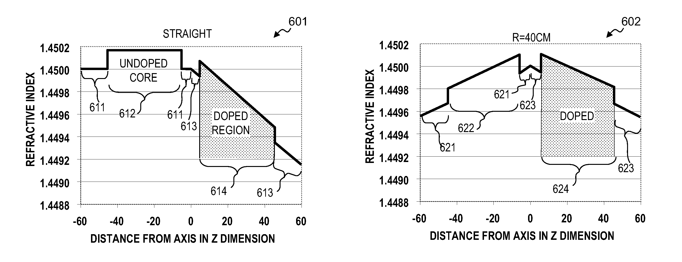
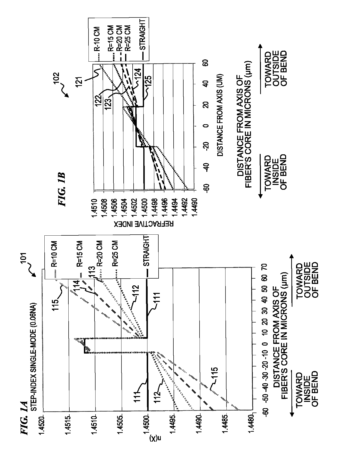
The present invention provides improved amplification characteristics in an optical-fiber amplifier that has a large mode area (LMA) core. This is achieved by compensating for the index of refraction changes that occur when the fiber is bent or coiled. The asymmetry in the index profile or doping profile of the fiber compensates for the index changes introduced by bending or cooling the fiber. The resulting effective index of the fiber is reduced on the outside of the bend or coil, which causes the signal mode to move to the higher index portion of the fiber. The fiber can be coiled without keeping it straight, as long as the asymmetry in the index profile or doping profile is maintained. The resulting fiber has a radially symmetric index profile and is designed to support the highest-order mode. The asymmetry in the index profile or doping profile can be set during fiber drawing to maintain the desired orientation. The fiber can also be designed to have a reduced effective index profile in the coiled section, suppressing other modes that could be in the core.

Problems solved by technology

In recent years, fiber lasers have deployed in applications requiring increasing average power, peak power and pulse energy, often while also requiring near-diffraction-limited beam quality.
Such methods do not allow one side of the cladding to have a different index than another side of the cladding, nor do they allow one side of the core to have a different refractive index or active-species doping than another side of the core.

Method used


Image

  • Apparatus and method for compensating for and using mode-profile distortions caused by bending optical fibers
  • Apparatus and method for compensating for and using mode-profile distortions caused by bending optical fibers
  • Apparatus and method for compensating for and using mode-profile distortions caused by bending optical fibers

Examples


Embodiment Construction

Although the following detailed description contains many specifics for the purpose of illustration, a person of ordinary skill in the art will appreciate that many variations and alterations to the following details are within the scope of the invention. Accordingly, the following preferred embodiments of the invention are set forth without any loss of generality to, and without imposing limitations upon the claimed invention.

In the following detailed description of the preferred embodiments, reference is made to the accompanying drawings that form a part hereof, and in which are shown by way of illustration specific embodiments in which the invention may be practiced. It is understood that other embodiments may be utilized and structural changes may be made without departing from the scope of the present invention.

The leading digit(s) of reference numbers appearing in the Figures generally corresponds to the Figure number in which that component is first introduced, such that the ...


PUM

PropertyMeasurementUnit
diametersaaaaaaaaaa
diametersaaaaaaaaaa
diametersaaaaaaaaaa

Abstract

An apparatus and method for compensating for mode-profile distortions caused by bending optical fibers having large mode areas. In various embodiments, the invention micro-structures the index of refraction in the core and surrounding areas of the inner cladding from the inner bend radius to the outer bend radius in a manner that compensates for the index changes that are otherwise induced in the index profile by the geometry and / or stresses to the fiber caused by the bending. Some embodiments of an apparatus and method include a fiber having a plurality of substantially parallel cores, the fiber including a straight section and a curved section; guiding signal light primarily in a second core in the straight section; guiding the signal light from the second core into a first core between the straight section and the curved section; and guiding the signal light primarily in the first core in the curved section.

Description

FIELD OF THE INVENTIONThe invention relates generally to optical-fiber amplifiers and more particularly to devices and methods of operation and apparatus and methods to make and use large-mode-area (LMA) fiber amplifiers and devices using LMA fiber amplifiers that are coiled but include a fiber structure that mitigates bend-loss and / or mode distortion in the core.BACKGROUND OF THE INVENTIONThere is a need for improved high-power pulse generation for a number of applications, including LIDAR (light detection and ranging) and in particular LADAR (laser detection and ranging) for detecting objects (particularly flying objects) at great distances, as well as for medical treatments and materials processing. There is also a need for high average power continuous-wave (CW) sources capable of narrow-line operation for applications such as directed energy.Optical amplifying fibers can have very high gain. When pumping such fibers to very high powers, the high power per area in the core cause...

Claims


Application Information

Patent Timeline
Patent Type & Authority Patents(United States)
IPC IPC(8): H04B10/17G02B6/036G02B6/028G02B6/14
CPCC03B37/0122G02B6/449G02B6/02333G02B6/02371H01S3/06716H01S3/06737H01S3/06741G02B6/02042G02B6/02295G02B6/028G02B6/0283G02B6/036G02B6/4478C03B37/01222C03B2201/08C03B2201/31C03B2201/32C03B2201/36C03B2203/12C03B2203/18C03B2203/22C03B2203/42H01S3/06704H01S3/06758H01S3/1067H01S3/1618H01S2301/02H01S2301/04G02B6/02338G02B6/02357G02B6/0281
Inventor MINELLY, JOHN D.
Owner LOCKHEED MARTIN CORP
Learn More