LED warning signal and light supports

a warning signal and light support technology, applied in the direction of identification means, instruments, mobile visual advertising, etc., can solve the problems of increasing the size of the light bar or emergency light, adversely affecting the drag characteristics of the light bar, and relying on mechanical components to revolve, so as to achieve the effect of easy customization by the user

Inactive Publication Date: 2003-08-21
SAFARILAND
View PDF0 Cites 75 Cited by
  • Summary
  • Abstract
  • Description
  • Claims
  • Application Information

AI Technical Summary

Benefits of technology

[0013] Still another object of an embodiment of the invention is to produce relatively lower amounts of electromagnetic emissions.
[0014] Another object of an embodiment of the invention is to be rugged and have a relatively longer life span than traditional warning signal lights.
[0016] Still another object of an embodiment of the invention is to allow the user to adjust the color of the light signal without having to make a physical adjustment from a multi-colored panel.
[0018] Yet another object of an embodiment of the invention is that the light signal produced can be easily customized by the user via a microprocessor.
[0026] Still another feature of an embodiment of the invention is the provision of an LED support member which may be easily connectable and / or removed from a transportable support such as a tripod for placement of an LED warning signal light at any location as desired by an individual.
[0027] Still another feature of an embodiment of the invention is the provision of an LED support member which may be easily connectable to an emergency vehicle, including but not limited to automobiles, ambulances, trucks, motorcycles, snowmobiles, and / or any other type of vehicle in which warning signal or emergency lights are utilized.

Problems solved by technology

Many problems exist with the known methods for producing warning light signals.
One particular problem with known light bars is their reliance on mechanical components to revolve or oscillate the lamps to produce the desired light signal.
Additionally, these components increase the size of the light bar or emergency lights which adversely affect its drag characteristics.
Moreover, there is an increased likelihood that a breakdown will occur requiring the repair or replacement of the defective component.
These lamps emanate large amounts of heat which is difficult to dissipate from the sealed light bar or emergency light and may damage the electronic circuitry contained therein.
In addition, these lamps consume large amounts of current requiring a large power supply or large battery or electrical source.
These lamps also generate substantial electromagnetic emissions which may interfere with radio communications.
Finally, these lamps, which are not rugged, have relatively short life spans necessitating frequent replacement.
Another problem with the known warning signal lights is their use of filters to produce the desired color.
Furthermore, filters fade or flake making them unable to consistently produce the desired color.
These problems associated with traditional signaling lamps are exacerbated by the fact that creating multiple light signals requires multiple signaling lamps.
Further, there is little flexibility in modifying the light signal created by a lamp.
For example, changing a stationary lamp into one that rotates or oscillates would require a substantial modification to the light bar which may not be possible.

Method used


Image

  • LED warning signal and light supports
  • LED warning signal and light supports
  • LED warning signal and light supports

Examples


Embodiment Construction

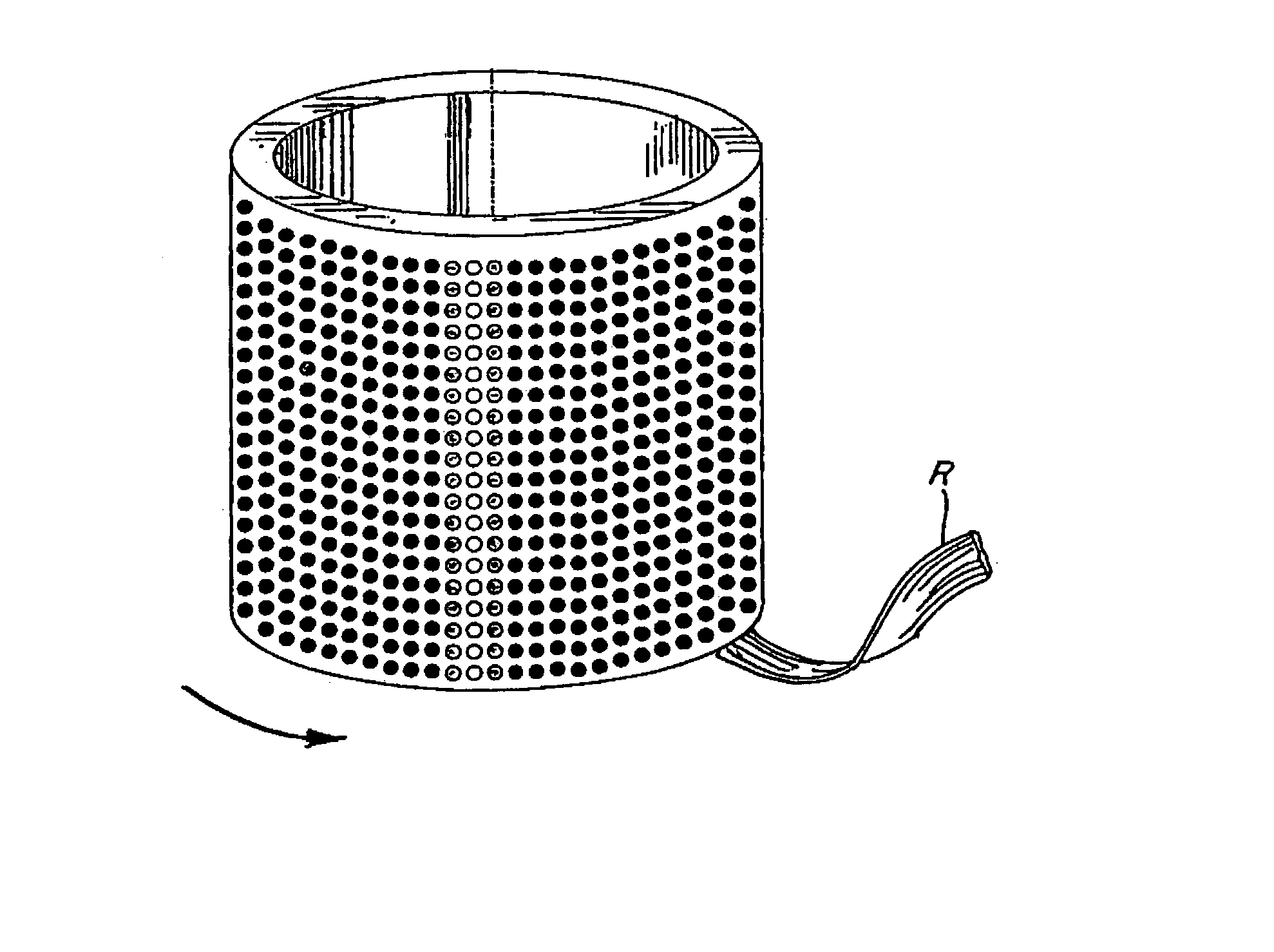
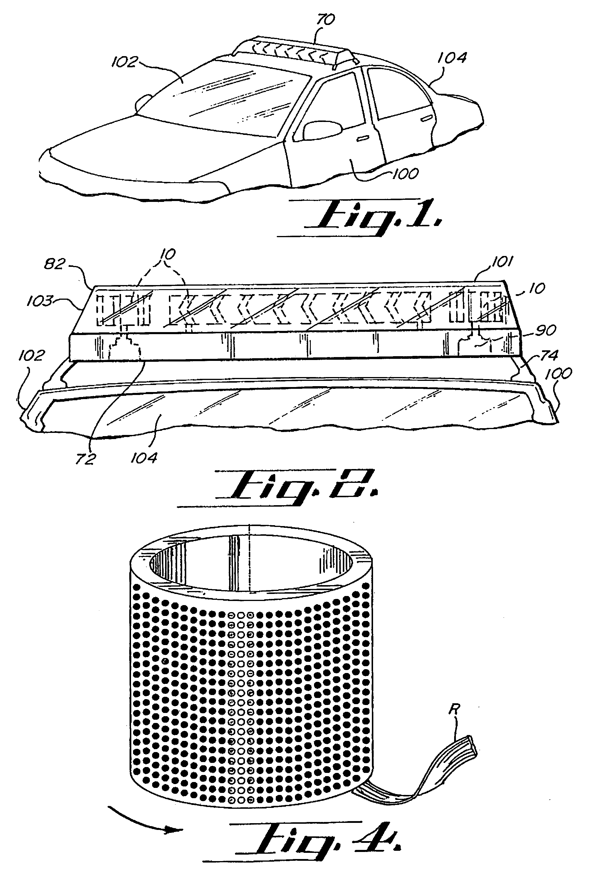
[0043] A warning signal light according to the principles of this invention is indicated generally as 10. FIGS. 1 and 2 depict light bar 70 mounted to an emergency vehicle 104. Light bar 70 includes base 72, mounting means 74, cover 82, and warning signal lights 10. Also included in light bar 70 are gyrators 90 used to impart motion to warning signal lights 10.

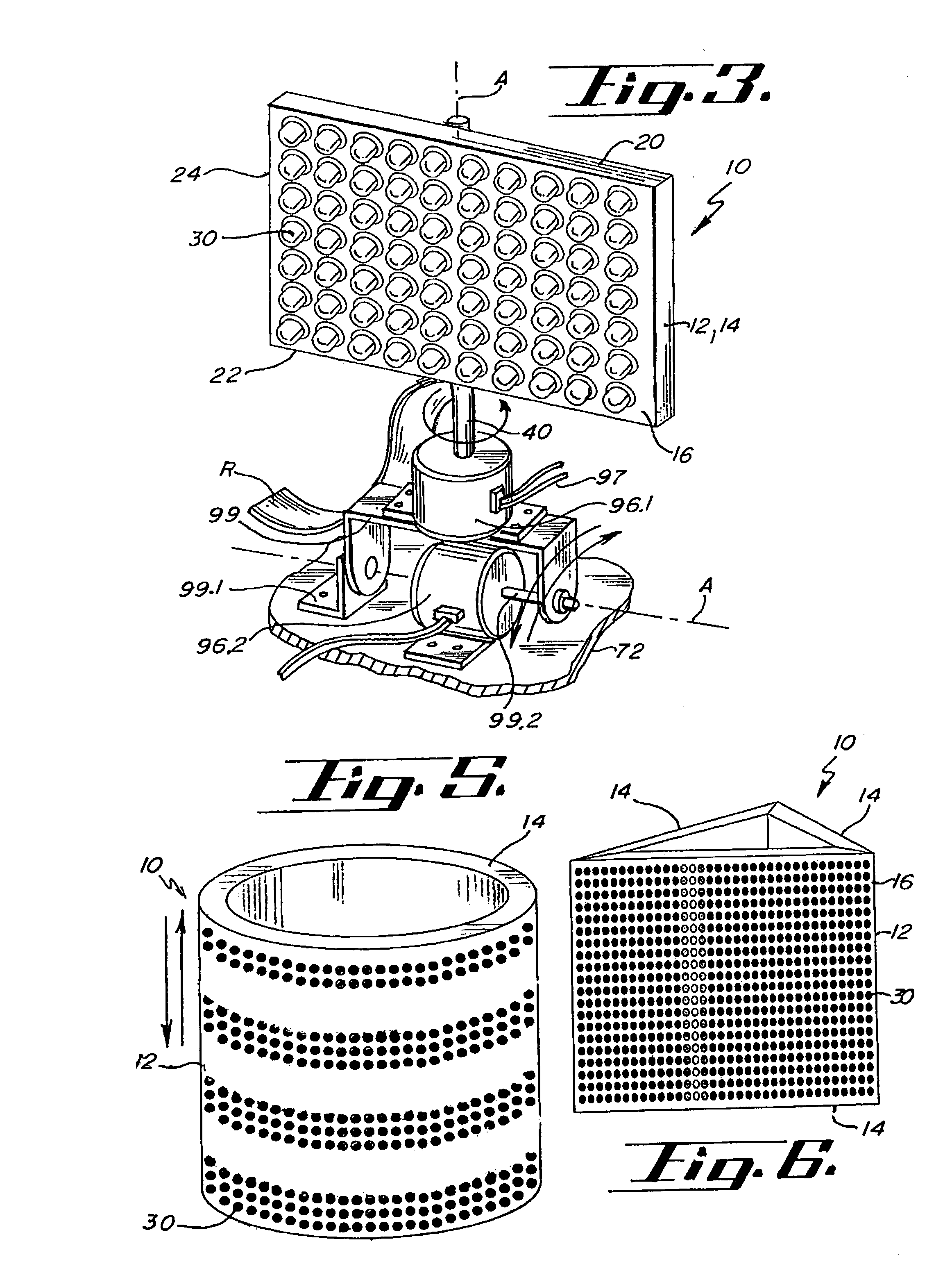
[0044] Referring to FIGS. 3 and 9, warning signal light 10 comprises light support 12, light sources 30, controller 50 (shown in FIG. 11), and connecting portion 40 for attaching the warning signal light to light bar 70 or gyrator 90. The warning signal light 10 operates to create a warning signal for use by an emergency vehicle by selectively activating light sources 30 using controller 50.

[0045] Light sources 30 are preferably light emitting diodes (LED's) and are generally arranged in aligned columns 32 and rows 34 as shown in FIGS. 7 and 9. Each of the light emitting diodes (LED's) may have shoulder portion 38 adjacent LED...


PUM


Abstract

A light emitting diode (LED) warning signal light, the warning signal light comprising an array of light sources configured on a light support and in electrical communication with a controller and a power supply, battery, or other electrical source. The warning signal light provides various colored light signals for independent use or use by an emergency vehicle. These light signals may include a stationary light, strobe light, revolving light, and an oscillating light. Additionally, the warning signal light may be capable of displaying symbols, reverse characters, or arrows. Preferably, rotating and oscillating light signals are produced by sequentially illuminating columns of LED's on a stationary light support. However, the warning signal light may also be rotated or oscillated via mechanical means. The warning signal light may also be transportable for easy connection to a stand such as a tripod for electrical connection to a power supply as a stand-alone warning signal.

Description

[0001] The present invention relates to a light emitting diode (LED) warning signal light for use by emergency vehicles and is based upon Provisional U.S. Patent Application No. 60 / 062,559, filed Oct. 21, 1997, and Provisional U.S. Patent Application No. 60 / 094,803, filed Jul. 31, 1998.BACKGROUND OF THE INVENTION[0002] Light bars or emergency lights of the type used on emergency vehicles such as fire trucks, police cars, and ambulances, utilize warning signal lights to produce a variety of light signals. These light signals involve the use of various colors and patterns. Generally, these warning signal lights consist of revolving and oscillating lamps having reflective back support members and colored filters as depicted in U.S. Pat. No. 5,091,828.[0003] Many problems exist with the known methods for producing warning light signals. One particular problem with known light bars is their reliance on mechanical components to revolve or oscillate the lamps to produce the desired light s...

Claims


Application Information

Patent Timeline
Patent Type & Authority Applications(United States)
IPC IPC(8): B60Q1/26F21S8/00G08B5/22G08B5/38G09F9/33G09F21/04
CPCB60Q1/2611B60Q1/2696F21W2111/00F21Y2101/02Y10S362/80G08B5/38G09F9/33G09F21/04F21Y2111/005F21Y2107/30F21Y2115/10G09F21/042
Inventor PEDERSON, JOHN C.
Owner SAFARILAND
Why Eureka
Try Eureka