Method and Arrangement in a Wireless Communication Network

a wireless communication network and wireless communication technology, applied in the direction of radio transmission, electrical equipment, transmission, etc., can solve the problems of unsatisfactory performance loss, all transmission performance suffers, and prolongs the over all transmission time, so as to achieve the effect of improving performance within the wireless communication network

Active Publication Date: 2011-12-01
TELEFON AB LM ERICSSON (PUBL)
View PDF5 Cites 36 Cited by
  • Summary
  • Abstract
  • Description
  • Claims
  • Application Information

AI Technical Summary

Benefits of technology

[0019]Embodiments of the present method and relay may implemented such that 3GPP-compliant type-I relay in half duplex mode is the basic functionality, while full-duplex mode provides added value.
[0020]Thereby, thanks to the present method, transmission in full duplex mode in the relay node is possible, which allows communication in both directions, uplink and downlink, simultaneously. There are several benefits to using full-duplex over half-duplex. First, time is not wasted, since no frames need to be retransmitted, as there are no collisions. Second, the full data capacity is available in both directions because the send and receive functions are separated. Third, nodes do not have to wait until other nodes complete their transmission, since transmission is possible only in one direction at the time for each pair of sender / receiver.
[0021]Thus an improved performance within a wireless communication network is provided.

Problems solved by technology

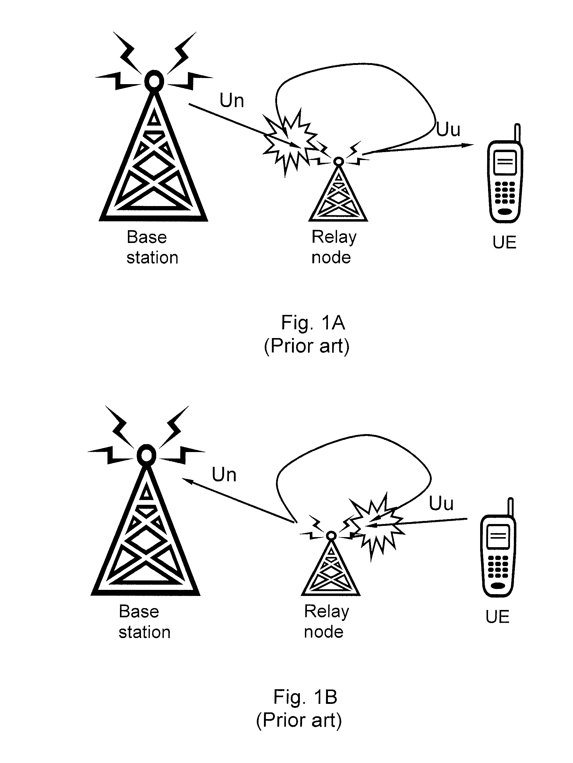
Though network deployment efforts and hardware requirements may not be a problem for type-I relay, such a half-duplex mechanism leads to undesirable performance loss, as resources have to be partitioned between Un and Uu.
Thus the over all transmission performance is suffering, in comparison with transmission in full duplex mode, which allows communication in both directions simultaneously.
Another problem with the known solution for avoiding self interference at the relaying node is that the time partitioning creates a delay of the transmission, which prolongs the over all transmission time.

Method used


Image

  • Method and Arrangement in a Wireless Communication Network
  • Method and Arrangement in a Wireless Communication Network
  • Method and Arrangement in a Wireless Communication Network

Examples


Embodiment Construction

d.

[0028]FIG. 4A is a combined flow chart and block diagram illustrating an embodiment of the present method.

[0029]FIG. 4B is a combined flow chart and block diagram illustrating an embodiment of the present method.

[0030]FIG. 5 is a combined flow chart and block diagram illustrating an embodiment of the present method.

[0031]FIG. 6 is a schematic flow chart illustrating embodiments of a method in a relay node.

[0032]FIG. 7 is a block diagram illustrating embodiments of an arrangement in a relay node.

[0033]FIG. 8 is a schematic flow chart illustrating embodiments of a method in a base station.

[0034]FIG. 9 is a block diagram illustrating embodiments of an arrangement in a base station.

DETAILED DESCRIPTION

[0035]The present solution is defined as a method and arrangement in a relay node and a method and arrangement in a base station, which may be put into practice in the embodiments described below. The present solution may, however, be embodied in many different forms and should not be co...


PUM


Abstract

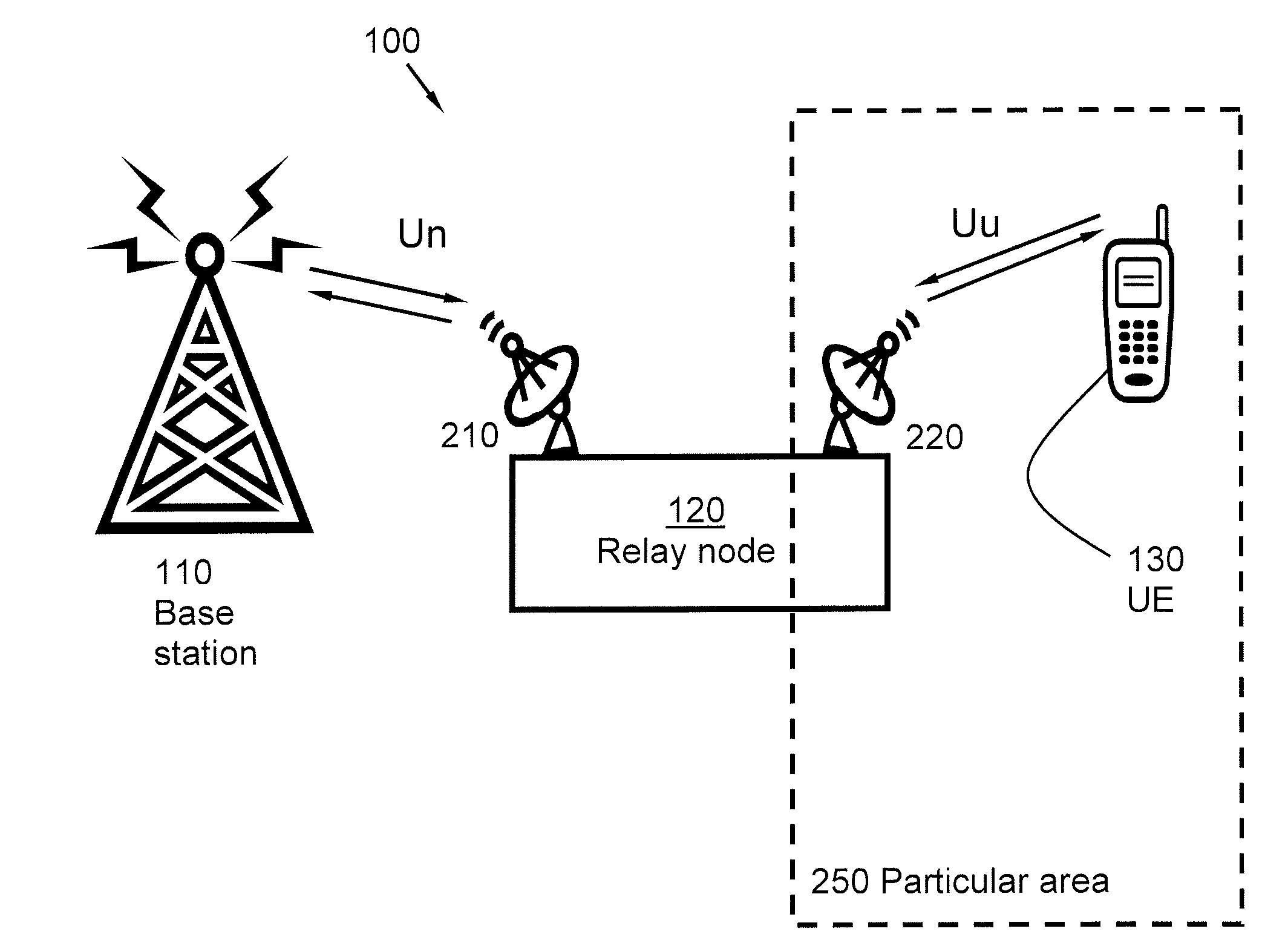
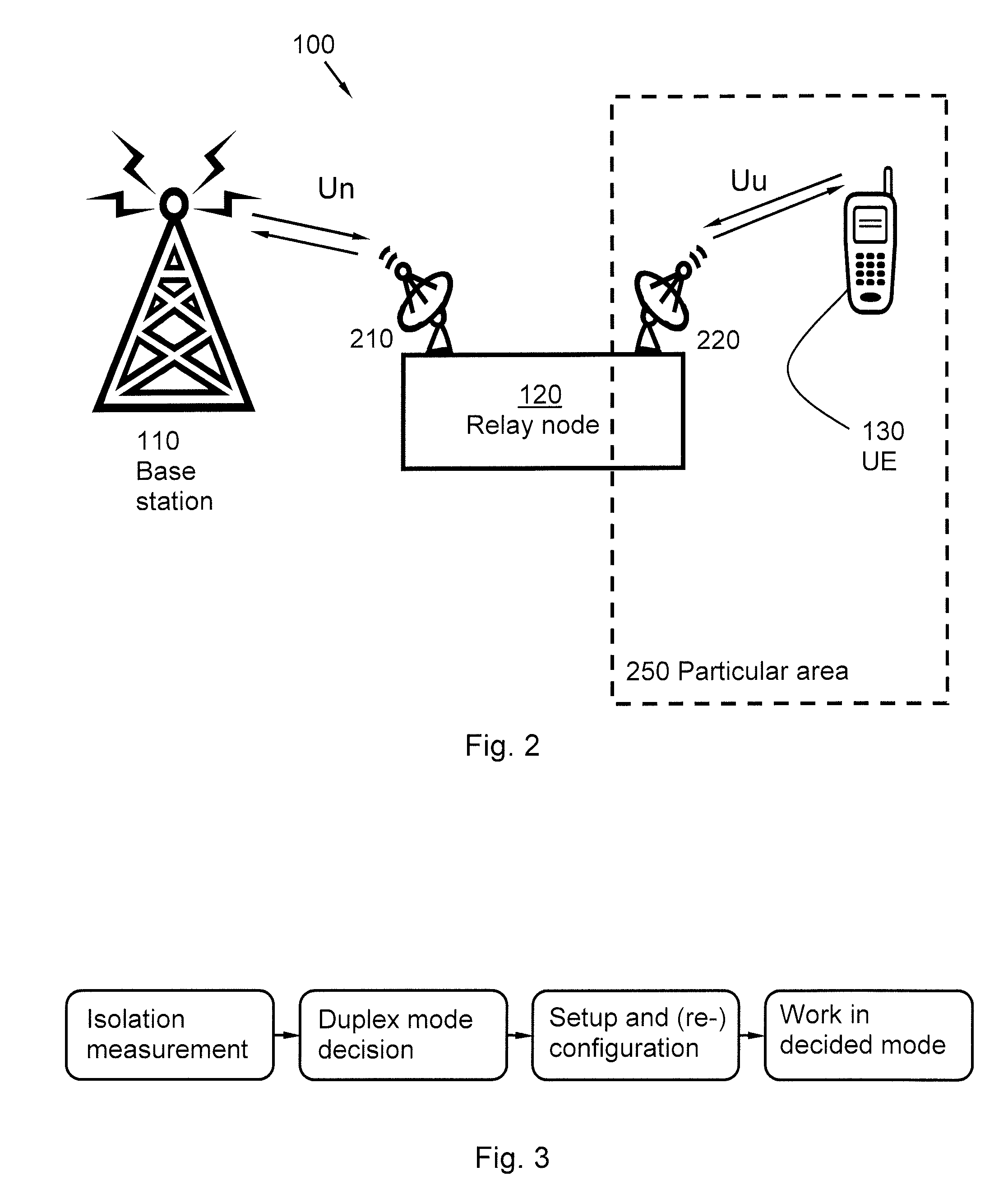
Method and arrangement in a relay node, for selecting communication mode. The relay node is configured to communicate with a base station via a donor antenna over a first link and to communicate with a user equipment via a coverage antenna over a second link. The method comprises obtaining an isolation value, based on the radio wave isolation between the relay donor antenna and the relay coverage antenna. The obtained isolation value is compared with an isolation threshold level value. The relay node is configured to communicate in full duplex mode if the obtained isolation value exceeds the isolation threshold level value, otherwise in half duplex mode. Information concerning the configured duplex mode of the relay node is transmitted to the base station.
Also a method and arrangement in a base station is described.

Description

TECHNICAL FIELD[0001]The present invention relates to a method and arrangement in a relay node and to a method and arrangement in a base station. More in particular, the present invention relates to a mechanism for selecting communication mode in the relay node.BACKGROUND[0002]Relaying is being considered e.g. for Long Term Evolution (LTE) Release 10, as a tool to improve the coverage of high data rates, group mobility, temporary network deployment, the cell-edge throughput and / or to provide coverage in new areas. At least type-1 relay nodes are part of LTE-Advanced, and a type-1 relay is an inband relaying node (RN), characterized by a serial of characteristics, e.g. having its own physical cell ID, appearing as a Rel-8 eNB to Rel-8 user equipments (UEs) etc.[0003]It is generally assumed in 3rd Generation Partnership Project (3GPP), which the LTE endeavourments form part of, that the transmission from any antenna of a relaying node may cause severe interference to the reception of ...

Claims


Application Information

Patent Timeline
Patent Type & Authority Applications(United States)
IPC IPC(8): H04W88/02
CPCH04B7/15564H04B7/15557
Inventor GAN, JIANSONGJOHANSSON, NIKLASLIU, YINMIAO, QINGYUMOBERG, PETERWANG, HAI
Owner TELEFON AB LM ERICSSON (PUBL)
Why Eureka
Try Eureka