
Image processing apparatus and method

a technology of image processing and image, applied in the direction of signal generators with optical-mechanical scanning, color television with bandwidth reduction, signal systems, etc., can solve the problems of difficult to increase the accuracy of intra-prediction and high inter-prediction accuracy, and achieve high encoding efficiency

Inactive Publication Date: 2011-12-01
SONY CORP
View PDF5 Cites 25 Cited by
  • Summary
  • Abstract
  • Description
  • Claims
  • Application Information

AI Technical Summary

Benefits of technology

The present invention relates to an image processing apparatus and method that can generate a high-accuracy prediction image without increasing processing load. The invention uses motion compensation and the orthogonal transform to generate a prediction image with reference frames. The residual between the prediction image and the actual image is encoded by using the correlation in the spatial and time directions. The invention also allows for the use of multiple reference frames and interpolation to improve the accuracy of motion compensation. The technical effect of the invention is to improve the accuracy of prediction images without increasing processing load.

Problems solved by technology

In general moving images, however, the prediction accuracy of inter-prediction is still higher because, for example, even considerably complicated texture would provide almost zero prediction residual as a result of inter-prediction although it is difficult to increase the accuracy of intra-prediction in the case of stationary texture in a screen.

Method used


Image

  • Image processing apparatus and method
  • Image processing apparatus and method
  • Image processing apparatus and method

Examples


first embodiment (

1. First embodiment (decoding process)

2. Second embodiment (encoding process)

third embodiment (

3. Third embodiment (modifications of filtering circuit)

first embodiment

1. First Embodiment

Overview of Prediction

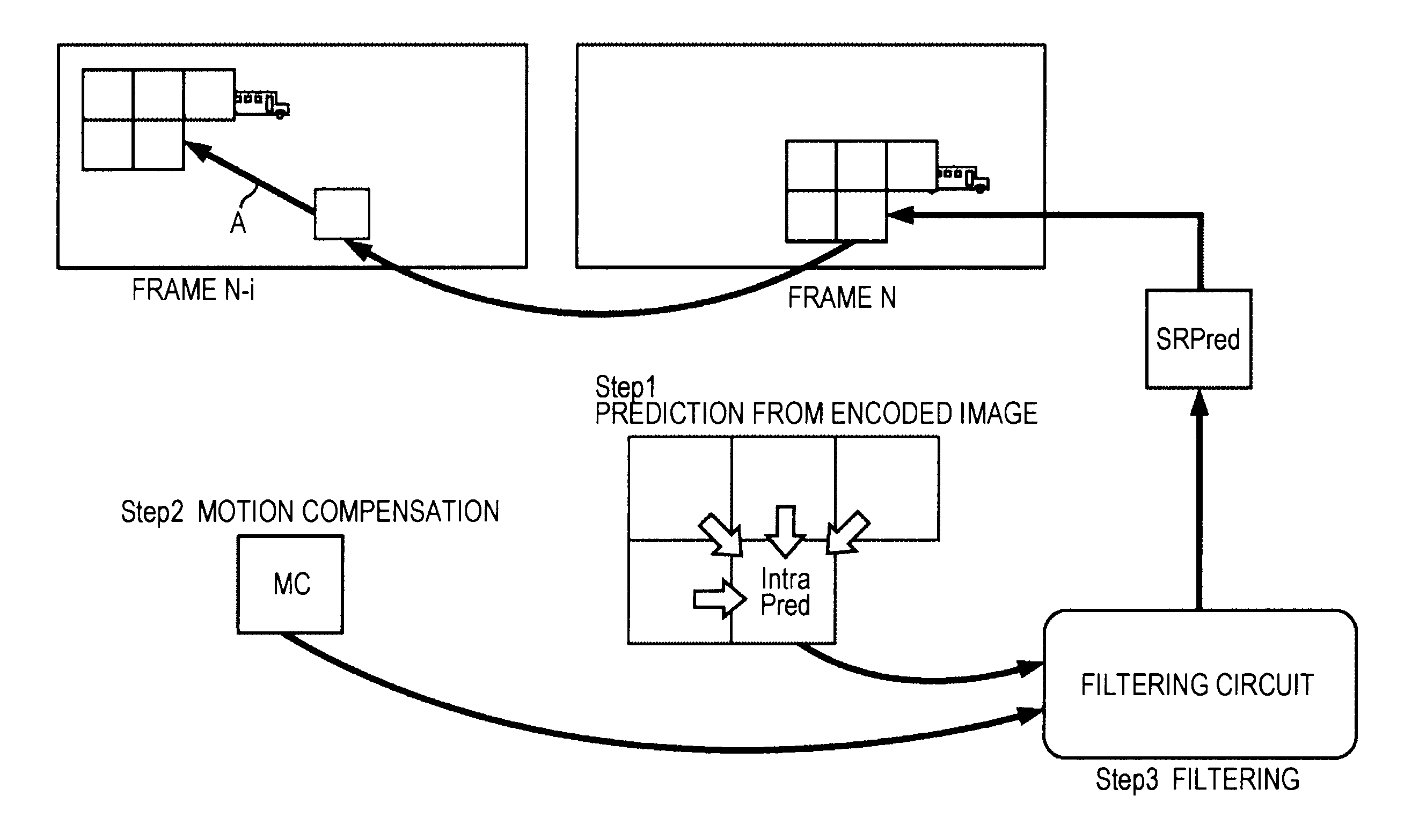
[0076]FIG. 4 is a diagram explaining an overview of a prediction image generation method to which the present invention is applied. In the present invention, in a decoder, at least one motion vector is transmitted through a bit stream in order to obtain a motion compensation image.

[0077]In FIG. 4, the way a single frame (N−1) is used for a reference plane for use in motion compensation in order to decode a frame N is illustrated. In FIG. 4, a motion vector for indicating the coordinates of an image to be subjected to motion compensation for the frame (N−1) is transmitted by a stream. The decoder uses this vector to obtain an image MC.

[0078]Furthermore, intra-prediction is performed utilizing a decoded pixel value in the frame N. In this prediction, for example, intra-prediction based on the H.264 standard is used. However, the present invention does not limit the type of intra-prediction process, and any prediction suitable for higher-accurac...


PUM


Abstract

The present invention relates to an image processing apparatus and method that can generate a high-accuracy prediction image with a small amount of control information.A motion compensation circuit 51 specifies a macroblock corresponding to a prediction image in a reference frame other than a current frame using a motion vector supplied from a prediction mode determination circuit 41. The motion compensation circuit 51 reads an image of the specified macroblock from a frame memory 19, and extracts the read image as a motion compensation image. An intra-prediction circuit 52 performs intra-prediction on the current frame using an arbitrary method to generate an intra-prediction image IP. The present invention can be applied to, for example, an encoding apparatus and a decoding apparatus.

Description

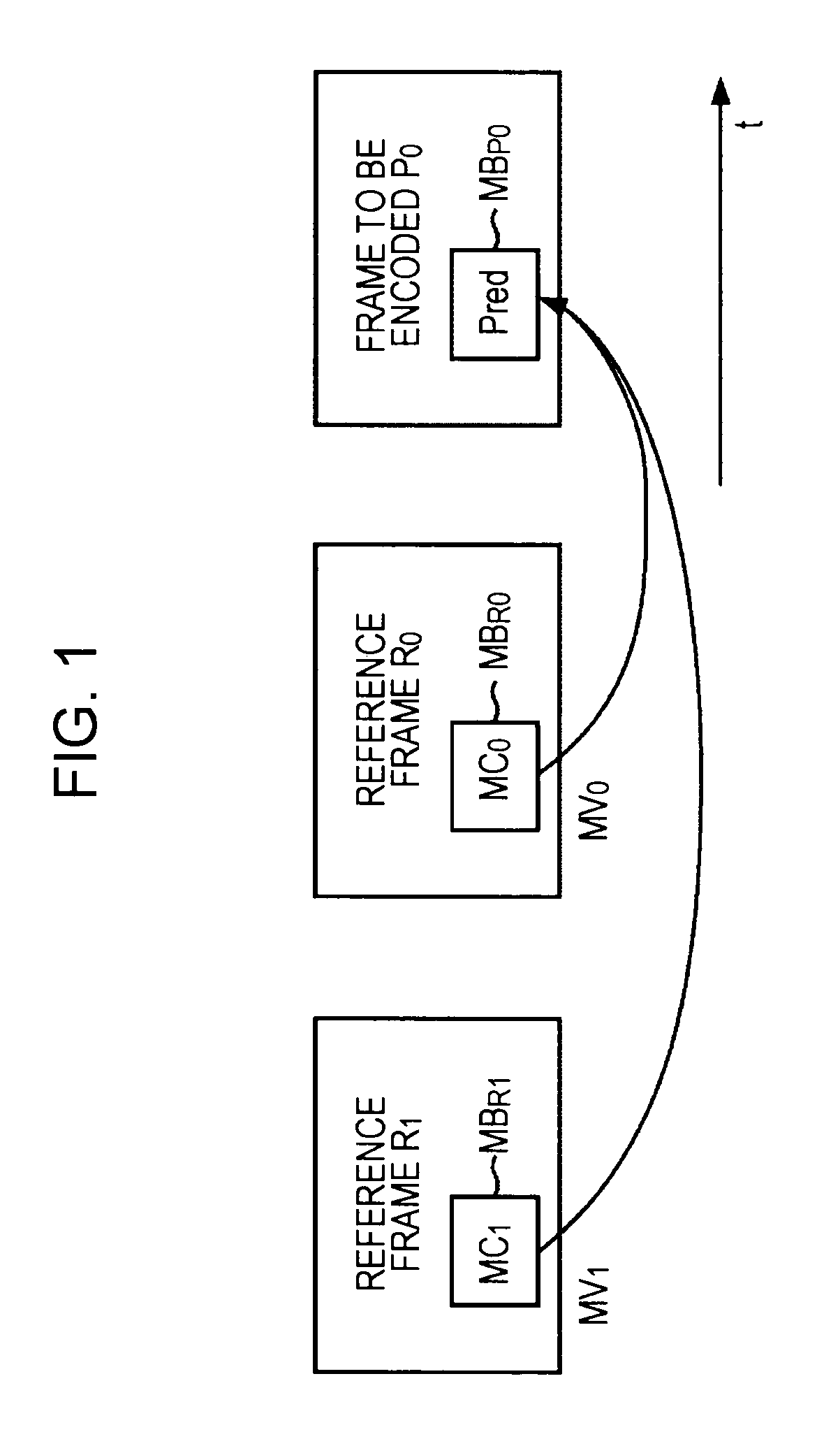
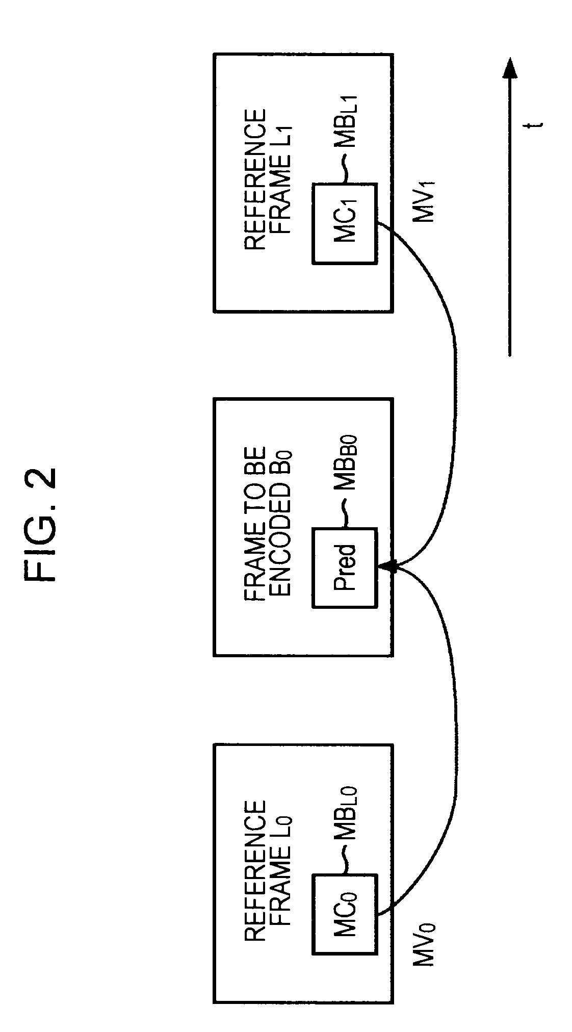
TECHNICAL FIELD[0001]The present invention relates to an image processing apparatus and method, and more specifically to an image processing apparatus and method that can generate a high-accuracy prediction image without increasing a processing load.BACKGROUND ART[0002]Conventionally, encoding schemes using motion compensation and the orthogonal transform such as the discrete cosine transform, Karhunen-Loève transform, or wavelet transform, including MPEG (Moving Picture Experts Group), H.26x, etc., have been generally utilized as encoding schemes in the case of handling moving images. In these moving image encoding schemes, the reduction in amount of code is achieved by utilizing the correlation in the spatial direction and time direction among the characteristics of an input image signal to be encoded.[0003]For example, in H.264, unidirectional prediction or bidirectional prediction is used when an inter-frame that is a frame to be subjected to inter-frame prediction (inter-predic...

Claims


Application Information

Patent Timeline
Patent Type & Authority Applications(United States)
IPC IPC(8): H04N7/32H04N19/50H04N19/107H04N19/117H04N19/134H04N19/136H04N19/176H04N19/196H04N19/46H04N19/503H04N19/593H04N19/60H04N19/61H04N19/70H04N19/80
CPCH04N19/503H04N19/63H04N19/593H04N19/107H04N19/615H04N19/117H04N19/82H04N19/573H04N19/577H04N19/109H04N19/159H04N19/103H04N19/51H04N19/105H04N19/513
Inventor NAKAGAMI, OHJIYAGASAKI, YOICHI
Owner SONY CORP
Learn More