Driving support device, driving support method, and program
Active Publication Date: 2011-12-01
PANASONIC CORP
View PDF8 Cites 113 Cited by
Summary
Abstract
Description
Claims
Application Information
AI Technical Summary
This helps you quickly interpret patents by identifying the three key elements:
Problems solved by technology
Method used
Benefits of technology
Benefits of technology
[0020]According to the present invention, by visualizing the distance from other vehicles present in the image as distance information in which a subject vehicle length is used as a reference unit of a length, the driver can more intuitively learn the distance from other vehicles. Thus, the driver can learn the distance and the relative speed at the time of lane change more intuitively, rapidly and reliably. Further, the driver can intuitively learn the distance to other vehicles while checking a status of the side rear and can more reliably perform a lane change operation.
Problems solved by technology
However, in the electronic mirror system, the side rear image displayed on the monitor is poorer in stereoscopic effect than a virtual image of the side rear seen through the side mirror, and it is difficult to measure the distance from a vehicle in an adjacent lane by merely displaying the captured image.
Method used
Image
Click on the blue label to locate the original text in one second.
Reading with bidirectional positioning of images and text.
Examples
embodiment 1
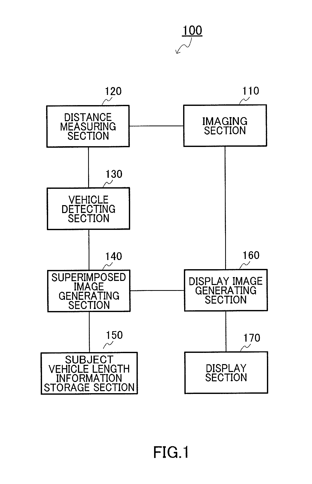
[0050]FIG. 1 is a block diagram showing a configuration of a drive support apparatus according to Embodiment 1 of the present invention. The present embodiment is an example in which an electronic mirror system that presents a driver with an image of a side rear area of a vehicle captured by a camera is applied.
[0051]As illustrated in FIG. 1, drive support apparatus 100 includes imaging section 110, distance measuring section 120, vehicle detecting section 130, superimposed image generating section 140, subject vehicle length information storage section 150, display image generating section 160, and display section 170.
[0052]Imaging section 110 is a stereo camera for visible light or infrared light for acquiring an image around a vehicle. Imaging section 110 horizontally reverses the side rear image of the captured image and then transfers the reversed side rear image to display image generating section 140 and distance measuring section 120 to be used as a base image of the electro...
embodiment 2
[0099]FIG. 7 shows a creating process of a superimposed image of the drive support apparatus according to Embodiment 2. FIG. 8 shows an example of a superimposed image of drive support apparatus.
[0100]A hardware configuration is similar to that of drive support apparatus 100 of FIG. 1. In the present embodiment, superimposed image generation 140 is different in a superimposed image generating operation.
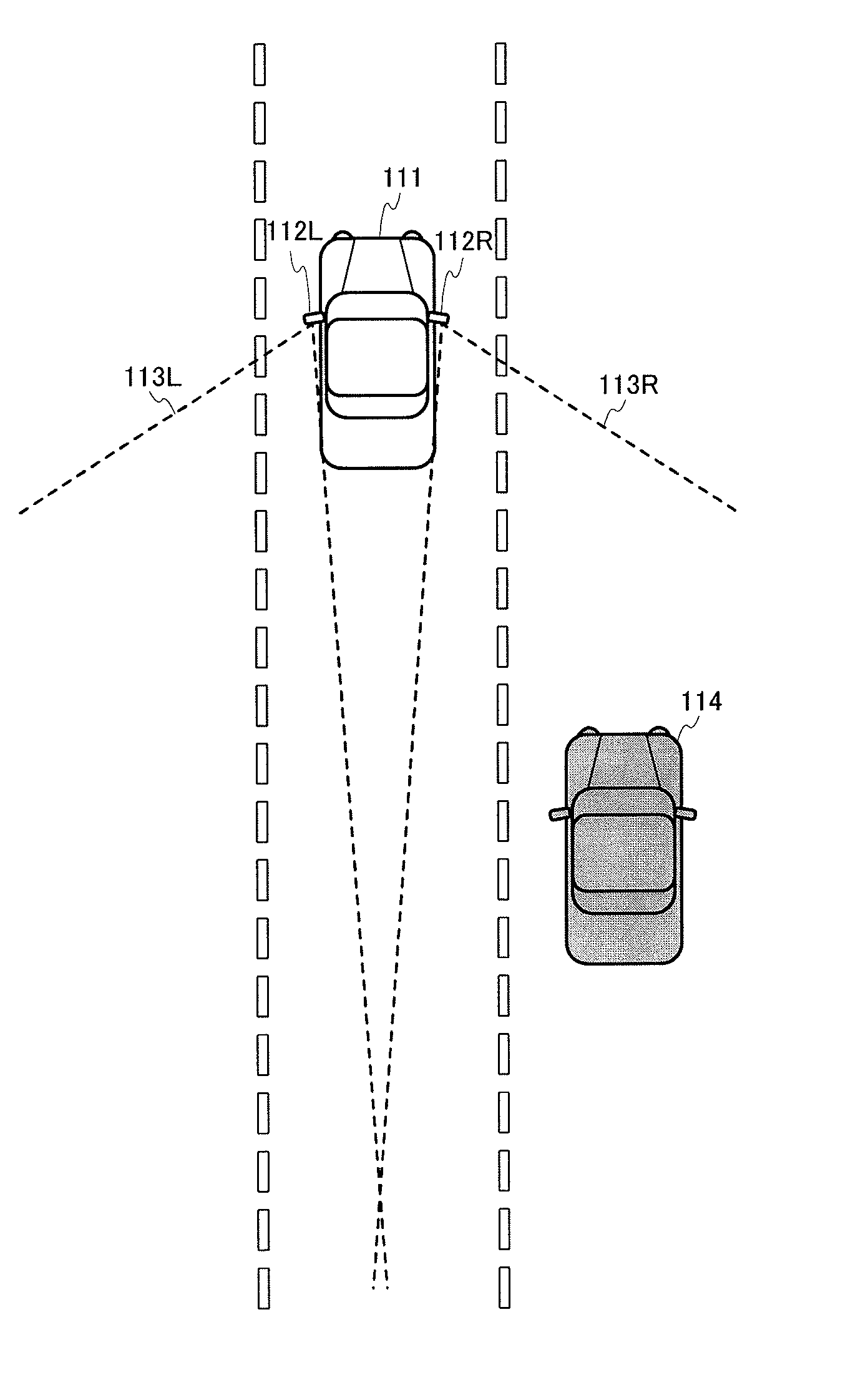
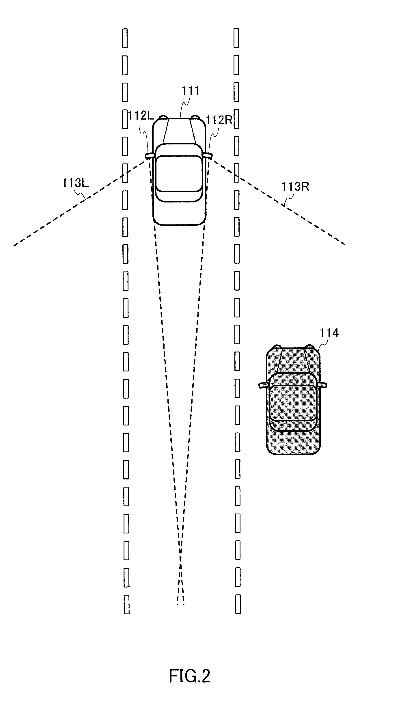
[0101]As illustrated in FIG. 7, distance lines 125-1 to 125-5 are assumed that are separated rearward at the same distance in a subject vehicle length unit behind line 121 of the subject vehicle's rear end, in field of view 113R of camera 112R that captures the right side rear, on a lane adjacent to the right of the present lane on which subject vehicle 111 is running. In this case, distance lines 125-1 to 125-5 are superimposed image.
[0102]It is assumed that in distance lines 125-1 to 125-5 assumed as described above, another vehicle 114 has been detected at the distance of 1.1 times...
embodiment 3
[0115]FIG. 9 is a flowchart showing an operation of drive support apparatus according to Embodiment 3 of the present invention. FIG. 9 illustrates a processing flow in which detection of a plurality of vehicles is considered. The same steps as in FIG. 3 are denoted by the same reference numerals.
[0116]A hardware configuration is similar to that of drive support apparatus 100 of FIG. 1. In the present embodiment, vehicle detecting section 130 detects a plurality of other vehicles based on the distance measuring result. Superimposed image generating section 140 generates the superimposed image on the closest vehicle.
[0117]In step S1, cameras 112L and 112R, that is, imaging section 110 acquires the stereo image at set timing and transmits the stereo image to distance measuring section 120 and display image generating section 160. Since imaging section is the stereo camera, two images are captured by one imaging section, but any one of the two images may be transmitted to display image ...
PUM
Abstract
Provided are a driving support device, a driving support method, and a program, in which the driver can more intuitively and accurately determine the distance to another vehicle in the side rear. A driving support device (100) is provided with an image-capturing section (110) for capturing side rear images of the vehicle, a distance measuring section (120) for measuring the distance between the vehicle and the another vehicle, and a vehicle detection section (130) for detecting the another vehicle in the captured images, wherein a superimposed image generating section (140) calculates the distance of units of the vehicle length units on the basis of information concerning the vehicle length stored in a vehicle length information storage section (150) and the distance to the another vehicle detected by the distance measuring section (120), and generates a superimposed image on the basis of the calculated distance. A display image generating section (160) synthesizes the generated superimposed image on a side peripheral image including the captured side rear images, and displays the image on a display section (170) installed in a position at which the field of front vision of the driver is not obstructed.
Description
TECHNICAL FIELD[0001]The present invention relates to a drive support apparatus, a driving support method, and a program. More particularly, the present invention relates to a drive support apparatus and a driving support method which present a driver with an image of a side rear area of a vehicle captured by a camera.BACKGROUND ART[0002]In recent years, as a camera technology advances and the cost decreases, various systems for supporting driving using a vehicle-mounted camera have been developed. Particularly, in a parking support system of a vehicle, by mounting a camera with a wide-angle lens, a driver can park a vehicle while checking an area including a rear blind spot which is difficult to see directly from the driver's seat.[0003]Patent Literature 1 discloses a parking assist device that draws guide lines of a vehicle width in a moving direction (a backward direction) of a vehicle and displays a ladder-shaped diagram, in a superimposed manner, in which the guide lines are co...
Claims
Application Information
Patent Timeline
Application Date:The date an application was filed.
Publication Date:The date a patent or application was officially published.
First Publication Date:The earliest publication date of a patent with the same application number.
Issue Date:Publication date of the patent grant document.
PCT Entry Date:The Entry date of PCT National Phase.
Estimated Expiry Date:The statutory expiry date of a patent right according to the Patent Law, and it is the longest term of protection that the patent right can achieve without the termination of the patent right due to other reasons(Term extension factor has been taken into account ).
Invalid Date:Actual expiry date is based on effective date or publication date of legal transaction data of invalid patent.

