Airless cosmetics applicator with airtight sealing dual cap

a technology of airtight sealing and cosmetics, which is applied in the field of apparatus improvement, can solve the problems of limited contamination entry into the product dispensing chamber, and achieve the effect of reducing eddies and possible backflow

Active Publication Date: 2011-12-01
COSMOPAK USA
View PDF5 Cites 13 Cited by
  • Summary
  • Abstract
  • Description
  • Claims
  • Application Information

AI Technical Summary

Benefits of technology

[0007]It is another object of the invention to provide a means for carefully controlling quantities of liquid or viscous semi-solid products dispensed onto a receiving surface.
[0011]It is also an object of the invention to provide a means that is adaptable to effectively delivering either a low viscosity or high viscosity product.
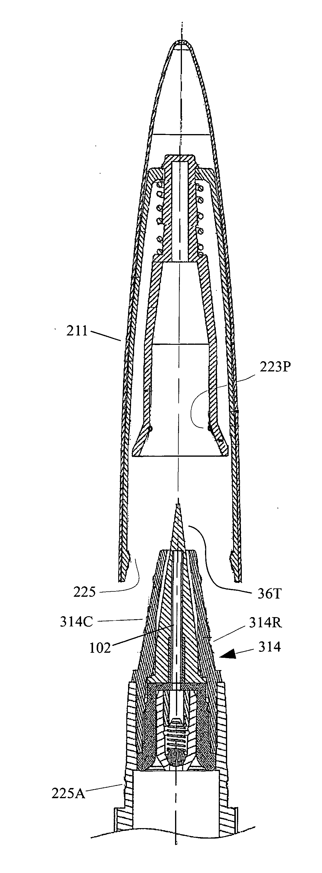
[0015]The cylinder head may contain a valve arrangement to permit flow of product from the product reservoir into a valve cylinder product pool, but prevent backflow which could cause contamination of the product supply. Additionally, flow of product from the valve cylinder product pool to a product dispensing chamber is limited by a narrow opening therebetween to reduce eddies and possible back-flow to prevent the possibility of any contamination that may be present within the product dispensing chamber from entering the valve cylinder product pool. The entry of contaminants into the product dispensing chamber may also be limited through the use of a dual inner / outer cap, where the inner cap may be spring biased relative to the outer cap, which is secured to the body. The spring biased inner cap also serves to prevent essential oils and moisture from escaping from the product dispensing chamber.

Problems solved by technology

The entry of contaminants into the product dispensing chamber may also be limited through the use of a dual inner / outer cap, where the inner cap may be spring biased relative to the outer cap, which is secured to the body.

Method used


Image

  • Airless cosmetics applicator with airtight sealing dual cap
  • Airless cosmetics applicator with airtight sealing dual cap
  • Airless cosmetics applicator with airtight sealing dual cap

Examples


first embodiment

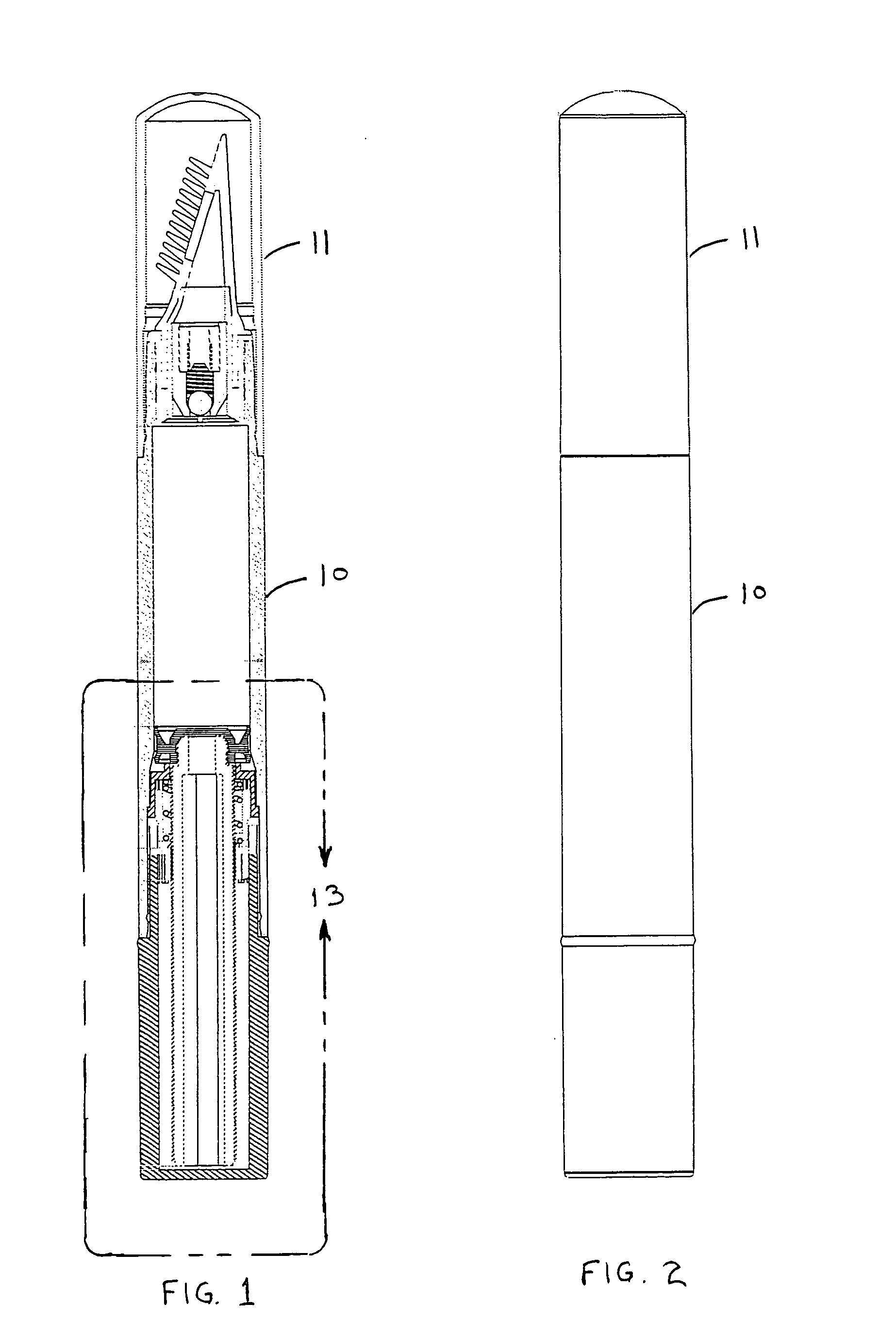
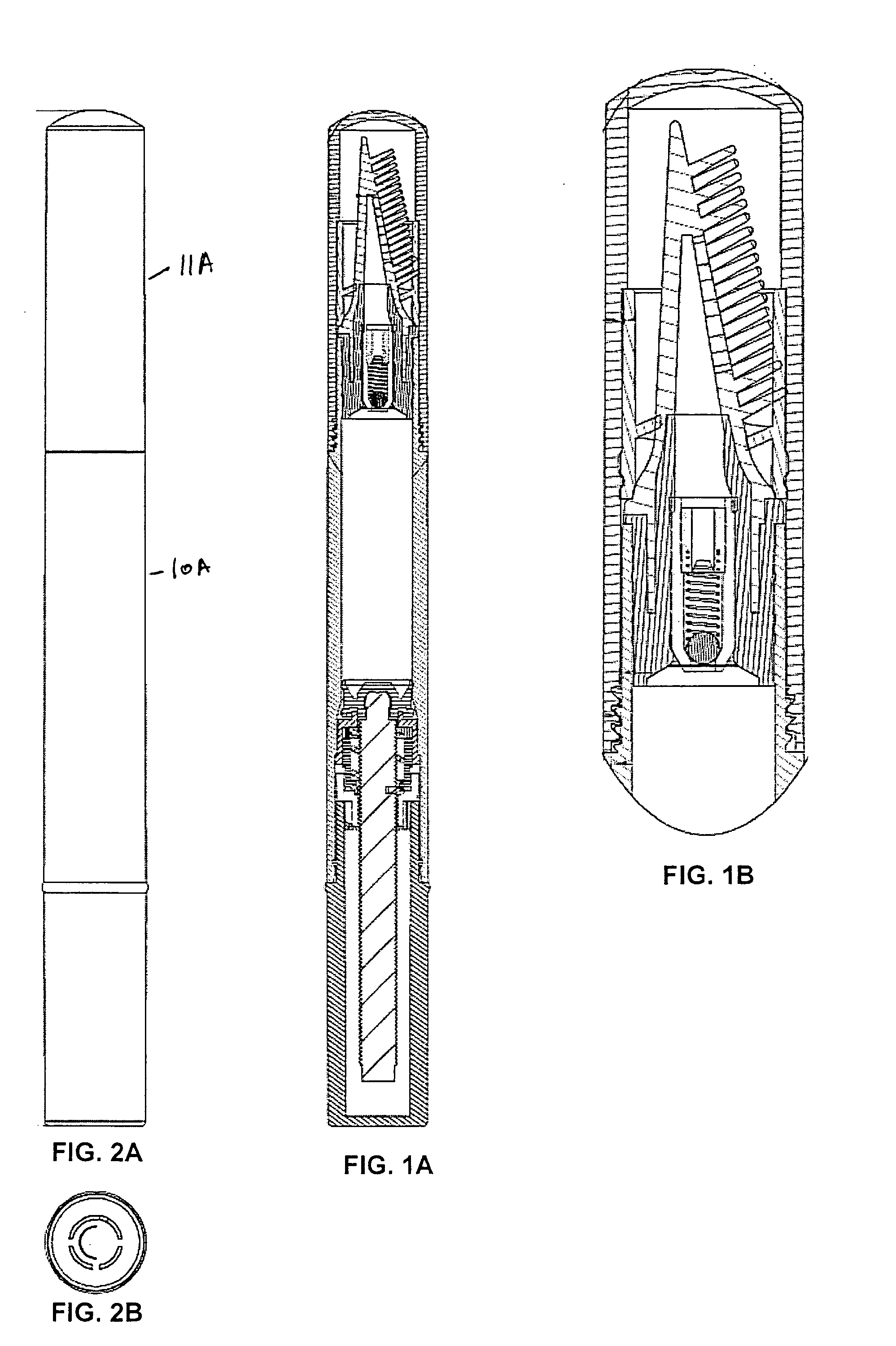
[0048]FIG. 1 shows the present invention, which includes an applicator device 10 with a cap 11. Assembly of the applicator device 10 is shown in the cross-sectional view of FIG. 3, and is broken down into its component parts—a body 17 and an applicator head 14—as seen in FIG. 4. The invention disclosed herein provides for various embodiments of the applicator head that may assemble into the body 17 in one of several ways to provide for careful dispensing of amounts of product to be delivered onto discrete surfaces of an object, or to provide for more generous delivery of a product onto a receiving surface, but while still be permitting deliberation with respect to where the product is applied. The invention also includes multiple product pooling areas to resist the spread of contaminants into the primary product pool, as well as a spring-biased dual cap that also serves to prevent the entry therein of contaminants, when secured onto the applicator, as well as serving to prevent the ...

embodiment 111

[0064]FIGS. 15A, 16A, 17A, and 18A also show another cap embodiment 111 being secured upon each of the applicator heads that were shown in FIGS. 15-18. Cap 111, which is shown by itself and enlarged in FIG. 20, may comprise an outer cap member 120, an inner cap support member 121, a helical spring 122, and an inner cap 123. The outer cap member 120 may receive an assembly of the other cap components as follows. The inner cap member 123 may comprise a shaft portion 123S, at the end of which may be a stop in the form of an integral retaining head 123R. The helical spring 122 may be slid onto the shaft portion 123S of the inner cap 123, after which the shaft portion 123S may be inserted through a hole in the inner cap support member 121, by press / shrink fit installing the integral retaining head 123R through the hole, as the integral retaining head may be hat-shaped to prevent its returning back through the hole. That assembly of cap components may then be installed within the outer ca...


PUM


Abstract

An airless applicator may deliver high / low viscosity liquids or semi-liquids, and contains a valve controlling flow between a product reservoir and an intermediate pooling area, while a narrow opening between the intermediate pooling area and a product dispensing chamber controls flow therebetween. This arrangement prevents backflow to the product reservoir, precluding an influx of contamination therein. Product delivery is by specially adapted applicator heads. In one embodiment, a plurality of prongs, and openings into the product dispensing chamber, permit application of mascara onto eyelashes. Alternating prong heights increases effectiveness in applying mascara onto all sides of a user's lashes. Other applicator heads are configured for lip product applications such as for lipstick, and for eye products such as eyeliner and eye shadow. An air-tight sealing cap having a spring biased inner cap member may prevent moisture from escaping from the product dispensing chamber and prevent entry of contaminants therein.

Description

CROSS REFERENCES TO RELATED APPLICATIONS[0001]This application is a continuation-in-part of U.S. patent application Ser. No. 12 / 925,164, having the title “Dual-Reservoir Mascara Applicator With Dispersive Product Delivery, filed Oct. 14, 2010, which claimed priority on U.S. Provisional Application Ser. No. 61 / 279,008, filed on Oct. 14, 2009, having the title, “Applicator Device with Dispersive Product Delivery,” with the disclosures of each being incorporated herein by reference.FIELD OF THE INVENTION[0002]The present invention relates to improvements in apparatus used for the application of liquids, creams, gels and the like, and more particularly to apparatus which comprise a valved dual reservoir system, and are capable of providing airless delivery of cosmetic products.BACKGROUND OF THE INVENTION[0003]There is a need to have a means of applying liquids, creams, ointments, lotions, gels, oils, paste, and the like, to a person's face, and other areas, and where such applications m...

Claims


Application Information

Patent Timeline
Patent Type & Authority Applications(United States)
IPC IPC(8): A45D40/26A45D34/04
CPCA45D34/042A45D2200/055A45D2200/051A45D40/262
Inventor DWYER, WALTER
Owner COSMOPAK USA
Why Eureka
Try Eureka