Composite aerofoil

a technology of aerofoil and composite material, which is applied in the direction of wind energy generation, liquid fuel engine components, non-positive displacement fluid engines, etc., can solve the problems of relative heavy weight and add to the weight of gas turbine engines

Inactive Publication Date: 2011-12-01
ROLLS ROYCE PLC
View PDF2 Cites 15 Cited by
  • Summary
  • Abstract
  • Description
  • Claims
  • Application Information

AI Technical Summary

Problems solved by technology

One problem with conventional solid low-pressure compressor blades, or fan blades, is that they are relatively heavy in weight due to their size.
Thus these features add to the weight of the gas turbine engine.

Method used


Image

  • Composite aerofoil
  • Composite aerofoil
  • Composite aerofoil

Examples


Embodiment Construction

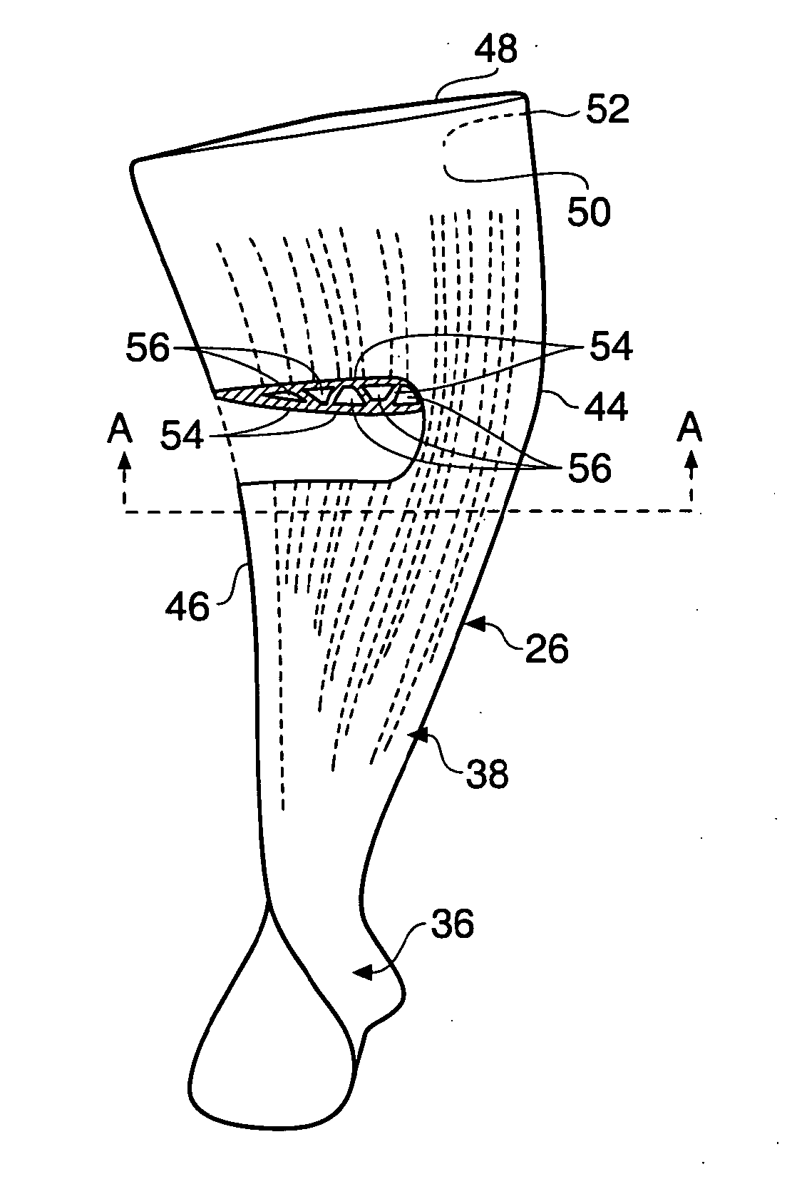
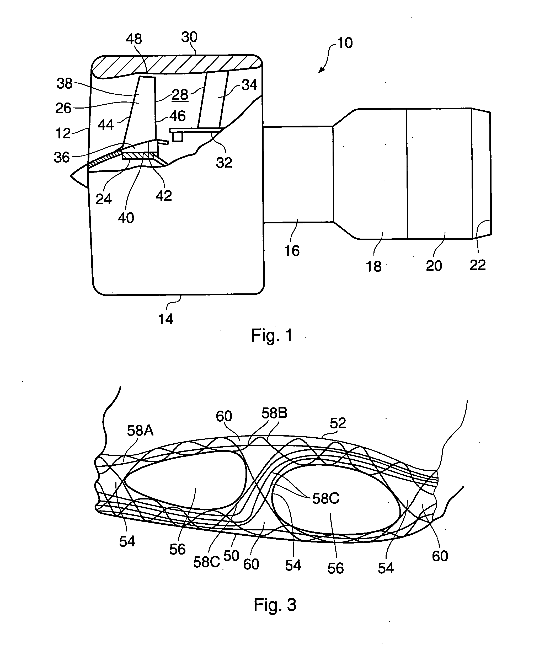
[0048]A turbofan gas turbine engine 10, as shown in FIG. 1, comprises in flow series an inlet 12, a fan section 14, a compressor section 16, a combustion section 18, a turbine section 20 and an exhaust 22. The fan section 14 comprises a fan rotor 24 carrying a plurality of circumferentially spaced radially outwardly extending fan blades 26. The fan blades 26 are arranged in a bypass duct 28 defined by a fan casing 30, which surrounds the fan rotor 24 and fan blades 26. The fan casing 30 is secured to a core engine casing 32 by a plurality of circumferentially spaced radially extending fan outlet guide vanes 34. The fan rotor 24 and fan blades 26 are arranged to be driven by a turbine (not shown) in the turbine section 20 via a shaft (not shown). The compressor section 16 comprises one or more compressors (not shown) arranged to be driven by one or more turbines (not shown) in the turbine section 20 via respective shafts (not shown).

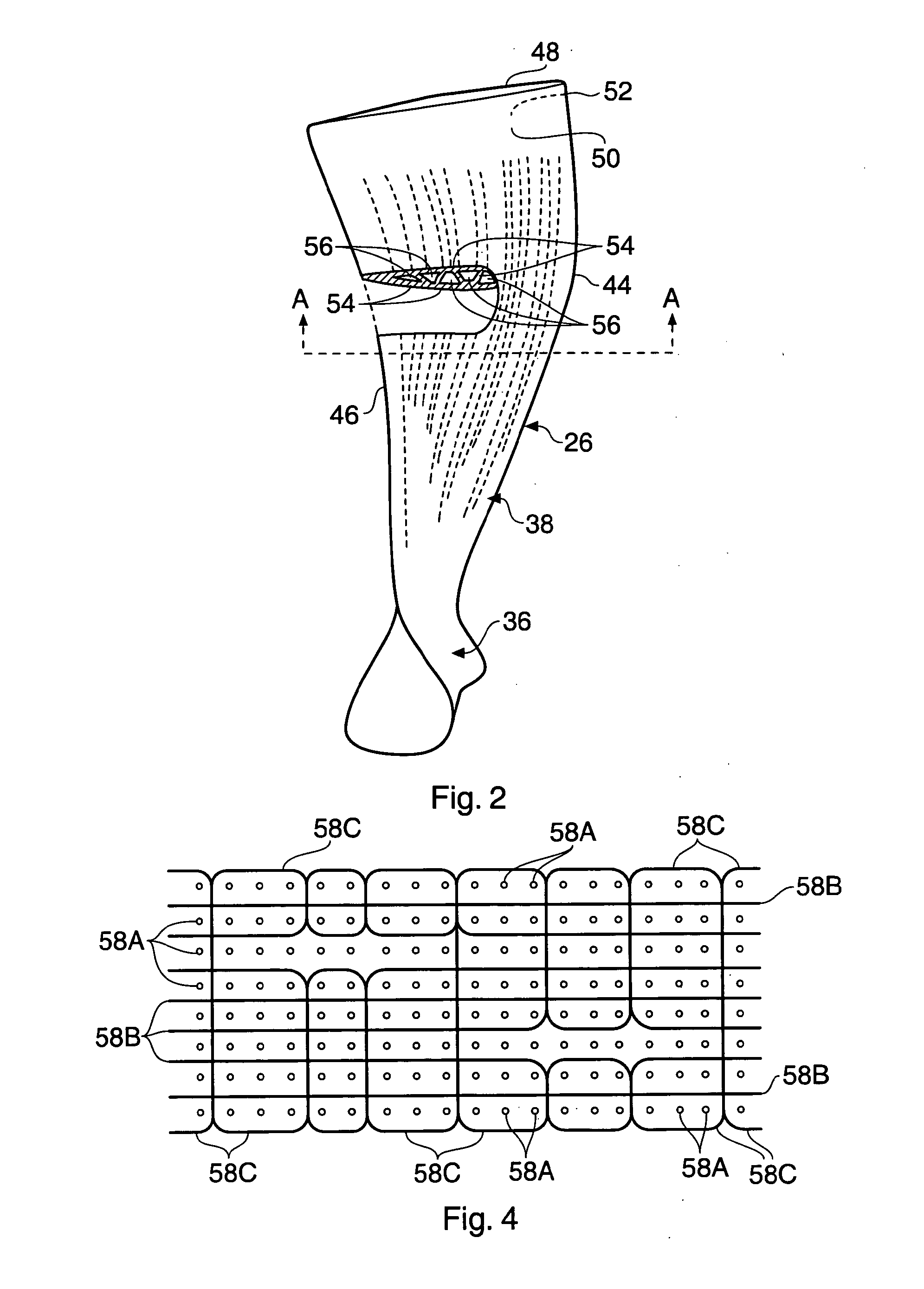
[0049]A fan blade 26 according to aspects of the pr...


PUM

PropertyMeasurementUnit
organicaaaaaaaaaa
densityaaaaaaaaaa
resilientaaaaaaaaaa

Abstract

A composite blade (26) comprises a three-dimensional arrangement of reinforcing fibres (58) and a matrix material (60) infiltrated around the three-dimensional arrangement of woven reinforcing fibres (60). The three-dimensional arrangement of woven reinforcing fibres (58) defines a plurality of cavities (56) within the aerofoil (28). The composite blade (26) comprises an aerofoil portion (38) and a root portion (36). The aerofoil portion (38) comprises a leading edge (44), a trailing edge (46), a concave pressure surface wall (50), a convex suction surface wall (52) and a tip (48). The aerofoil portion (36) comprises a plurality of webs (54) extending between, and being secured to, the concave pressure surface wall (50) and the convex suction surface wall (52) to produce a Warren girder structure. The three-dimensional arrangement of woven reinforcing fibres (58) are arranged to produce the concave pressure surface wall (50), the convex suction surface wall (52) and the plurality of webs (54). The matrix material (60) is an organic resin and the reinforcing fibres (58) comprise carbon fibres.

Description

CROSS-REFERENCE TO RELATED APPLICATIONS[0001]This application is a divisional of U.S. application Ser. No. 11 / 262,781, filed 1 Nov. 2005 and currently pending, which claims foreign priority to United Kingdom patent App'n Ser. No. GB 0424481.0, filed 5 Nov. 2004.BACKGROUND OF THE INVENTION[0002]The present invention relates to a composite aerofoil, in particular to a composite fan blade, for a gas turbine engine.[0003]Conventionally compressor blades, or fan blades, comprise forged, or machined, solid metal.[0004]One problem with conventional solid low-pressure compressor blades, or fan blades, is that they are relatively heavy in weight due to their size. The gas turbine engines to which these fan blades are secured require that the rotor disc is made sufficiently strong to carry the operational loads of the fan blades and this entails strengthening the rotor disc and as such means increasing the mass and weight of the rotor disc. In addition the gas turbine engines to which these f...

Claims


Application Information

Patent Timeline
Patent Type & Authority Applications(United States)
IPC IPC(8): F01D5/14F01D5/28
CPCB29C70/222Y02T50/433B29D99/0028B29L2031/08F01D5/147F01D5/282F05C2201/025Y02E10/721Y02T50/672Y02T50/673F05D2230/60F05D2240/301D03D25/005F05D2250/20F05D2250/293F05D2300/2283F05D2300/2261F05D2300/44F05D2300/603F05D2300/612F05D2300/614B29C70/865Y02E10/72Y02T50/40Y02T50/60Y10T442/20Y10T442/2975Y10T442/3195
Inventor MCMILLAN, ALISON J.
Owner ROLLS ROYCE PLC
Why Eureka
Try Eureka