Window System and Light Guiding Film Therein

Active Publication Date: 2011-12-08
INOMA
View PDF0 Cites 9 Cited by
  • Summary
  • Abstract
  • Description
  • Claims
  • Application Information

AI Technical Summary

Benefits of technology

[0010]In the present invention, the light guiding film can guide the

Problems solved by technology

Thus, the illuminatin

Method used


Image

  • Window System and Light Guiding Film Therein
  • Window System and Light Guiding Film Therein
  • Window System and Light Guiding Film Therein

Examples


Example

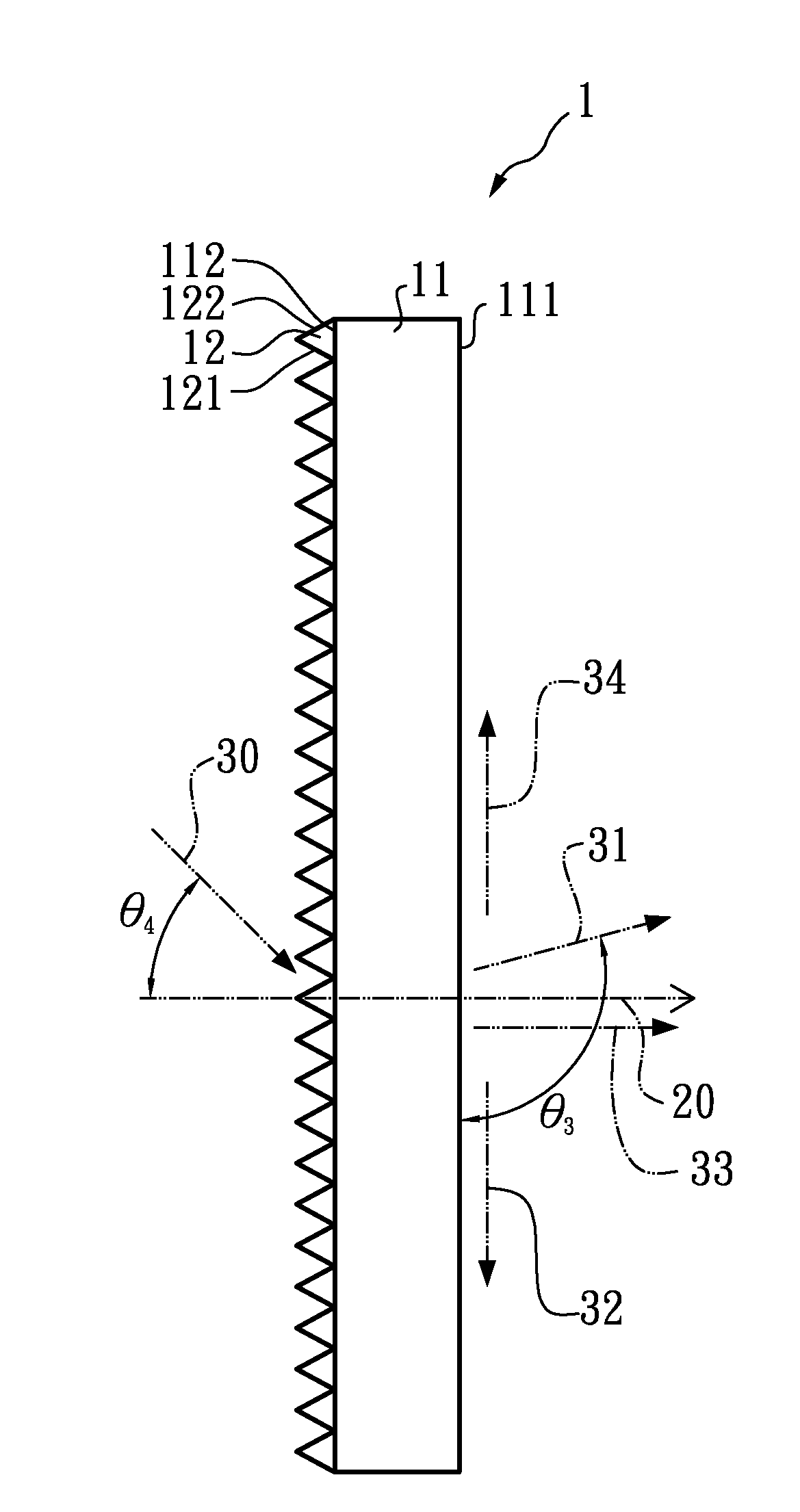
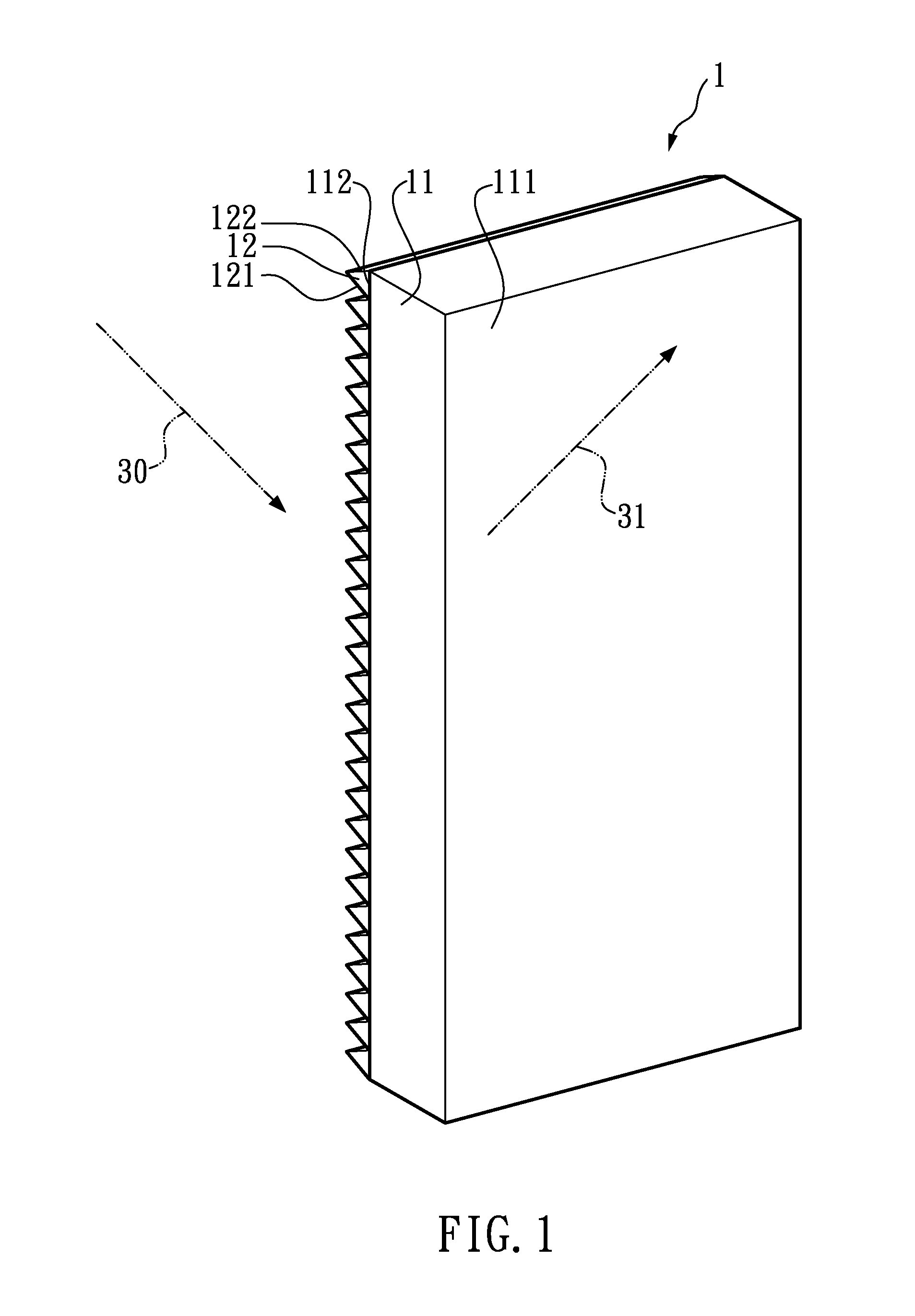
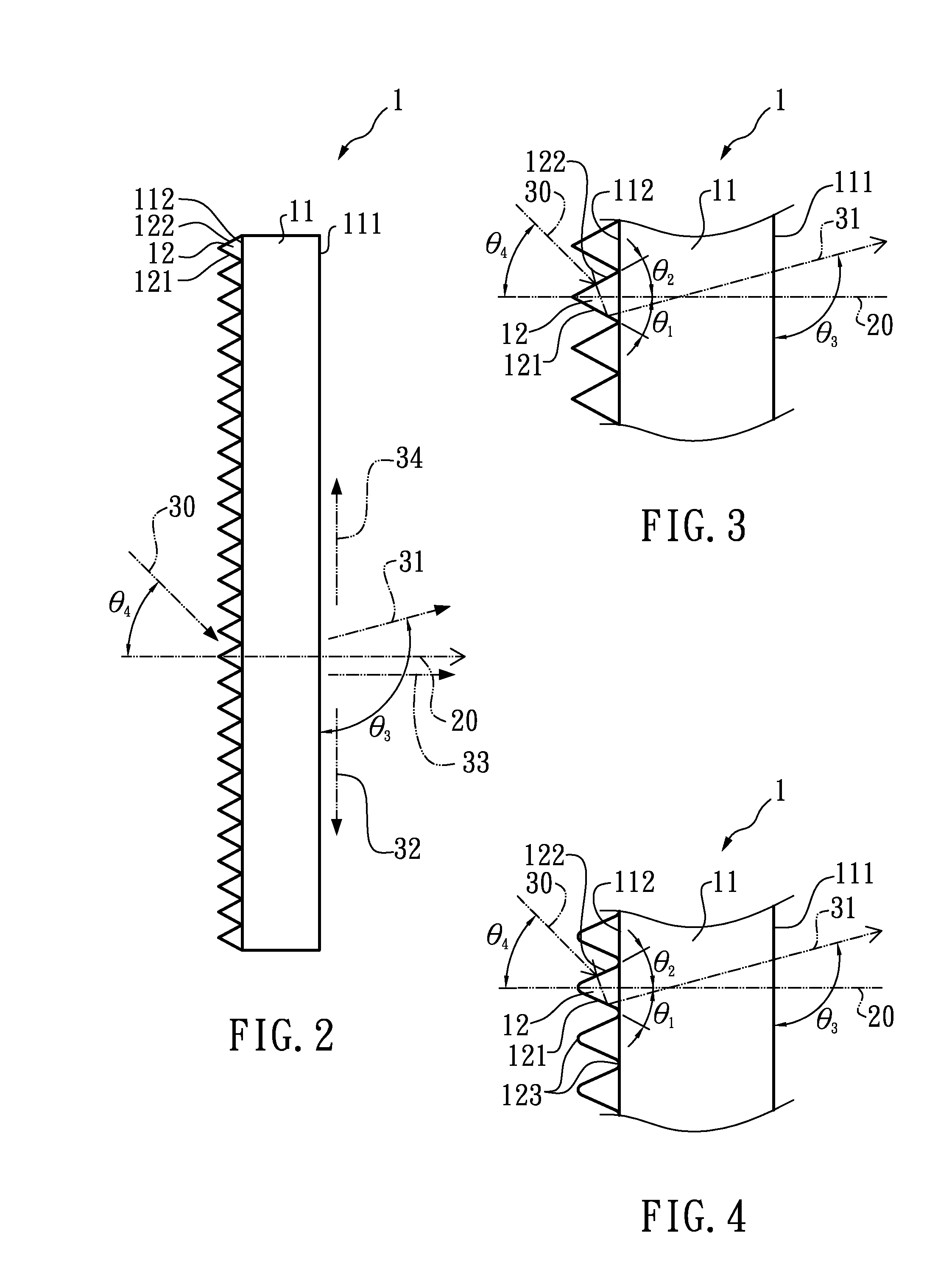
[0021]FIG. 1 shows a perspective view of a light guiding film according to a first embodiment of the present invention. FIG. 2 shows a side view of a light guiding film according to a first embodiment of the present invention. FIG. 3 shows a partially enlarged view of FIG. 2. The light guiding film 1 comprises a film base 11 and at least one microstructure 12. In the embodiment, the light guiding film 1 comprises a plurality of microstructures 12. The film base 11 has a first side 111 and a second side 112, and the second side 112 is opposite the first side 111.

[0022]The microstructure 12 is disposed on the second side 112 of the film base 11, and comprises a first surface 121 and a second surface 122. The second surface 122 is above the first surface 121. A reference plane 20 is defined as a phantom plane that is perpendicular with the first side 111 or the second side 112 of the film base 11. That is, when the light guiding film 1 stands upright, the reference plane 20 is a phanto...

Example

[0045]FIG. 8 shows a side view of a window system according to a fourth embodiment of the present invention. The window system 4 comprises a first protective plate 41, a first protective plate 42 and a light guiding film 1. The second protective plate 42 is fixed to the first protective plate 41 to form a closed space. The light guiding film 1 is the same as the light guiding film 1 (FIGS. 1 to 4) of the first embodiment, and is disposed in the accommodating space between the first protective plate 41 and the second protective plate 42. The light guiding film 1 comprises a film base 11 and at least one microstructure 12. The first protective plate 41, the second protective plate 42, the film base 11, and the microstructure 12 are light transmissible, and the second protective plate 42 faces the incident light beams 30. Preferably, the material of the first protective plate 41 and the second protective plate 42 are glass.

[0046]The light guiding film 1 is attached to the first protect...

Example

[0048]FIG. 9 shows a side view of a window system according to a fifth embodiment of the present invention. The window system 5 comprises a first protective plate 41, a first protective plate 42 and a light guiding film 3. The second protective plate 42 is fixed to the first protective plate 41 to form a closed space. The light guiding film 3 is the same as the light guiding film 3 (FIG. 7) of the third embodiment, and is disposed in the accommodating space between the first protective plate 41 and the second protective plate 42. The light guiding film 3 comprises a film base 11 and at least one microstructure 12. The first protective plate 41, the second protective plate 42, the film base 11, and the microstructure 12 are light transmissible, and the second protective plate 42 faces the incident light beams 30. Preferably, the material of the first protective plate 41 and the second protective plate 42 are glass.

[0049]The light guiding film 3 is attached to the second protective pl...


PUM


Abstract

The present invention relates to a light guiding film including a film base and at least one microstructure. The microstructure is disposed on a side of the film base, and comprises a first surface and a second surface. A first inclination angle is between the first surface and a reference plane, the reference plane is perpendicular with the film base, and a second inclination angle is between the second surface and the reference plane. The total energy of the output light beams with the output angles from 85 to 120 degrees is more than 40% of the total energy of the output light beams with the output angles from 0 to 180 degrees. Therefore, the light guiding film can guide the incident light beams into a room near horizontally and avoid glare.

Description

BACKGROUND OF THE INVENTION[0001]1. Field of the Invention[0002]The present invention relates to a window system and light guiding film therein, and more particularly to a window system and light guiding film capable of changing the direction of incident light.[0003]2. Description of the Related Art[0004]The conventional sunlight guiding apparatus is of various types, such as plate, shutter or film, which is disposed on or near a window of a room and used for guiding the sunlight beams outside the room into the room. The sunlight beams are directed to illuminate a reflector on the ceiling in the room. Then, the sunlight beams are reflected by the reflector, and used for indoor lighting or auxiliary illumination. In addition, in some of the conventional sunlight guiding apparatus, the sunlight beams are guided into the room directly without being reflected by the reflector on the ceiling.[0005]The conventional sunlight guiding apparatus can guide the direct light beams and the diffus...

Claims


Application Information

Patent Timeline
IPC IPC(8): G02B17/00E04C2/54
CPCG02B5/045G02B17/04G02B17/002G02B6/0038
Inventor TSAI, JUNG-LIEH
Owner INOMA
Why Eureka
Try Eureka