Methods and apparatus employing fec codes with permanent inactivation of symbols for encoding and decoding processes

a technology of fec codes and symbols, applied in the field of encoding and decoding data in communications systems, can solve the problems of low computational complexity of chain reaction encoding and decoding processes, source data might not be entirely recoverable, and relatively computationally intensive, so as to reduce the computational cost of encoding data for transmission over a channel, reduce the computational cost of decoding such data, and reduce the absolute and relative reception overhead

Active Publication Date: 2011-12-08
QUALCOMM INC
View PDF13 Cites 92 Cited by
  • Summary
  • Abstract
  • Description
  • Claims
  • Application Information

AI Technical Summary

Benefits of technology

[0032]Numerous benefits are achieved by way of the present invention. For example, in a specific embodiment, the computational expense of encoding data for transmission over a channel is reduced. In another specific embodiment, the computational expense of decoding such data is reduced. In another specific embodiment, the absolute and relative reception overhead is substantially reduced. Depending upon the embodiment, one or more of these benefits may be achieved. These and other benefits are provided in more detail throughout the present specification and more particularly below.

Problems solved by technology

Lost data (erasures) are often easier to deal with than corrupted data (errors) because the recipient cannot always tell when corrupted data is data received in error.
In a simple case, the encoded data is a copy of the source data, but if the received encoded data differs (due to errors and / or erasures) from the transmitted encoded data, in this simple case the source data might not be entirely recoverable absent additional data about the source data.
However, they can be fairly computationally intensive at times. A decoder might be able to decode more often, or more easily, if the source symbols are encoded using a static encoder prior to a dynamic encoder that encodes using a chain reaction or another rateless code.
Preferably, the computational complexity of performing chain reaction encoding and decoding processes is low.
In a typical system, a brute force implementation of this can consume excessive computing effort and memory requirements.
Of course, for a particular set of received encoded symbols, it might be impossible to recover all of the original input symbols, but even where it is possible, it might be very computationally expensive to compute the result.

Method used


Image

  • Methods and apparatus employing fec codes with permanent inactivation of symbols for encoding and decoding processes
  • Methods and apparatus employing fec codes with permanent inactivation of symbols for encoding and decoding processes
  • Methods and apparatus employing fec codes with permanent inactivation of symbols for encoding and decoding processes

Examples


example hardware

Components

[0224]FIGS. 30-31 illustrate block diagrams of hardware that might be used to implement methods described above. Each element can be hardware, program code or instructions executed by a general purpose or custom-purpose processor or a combination.

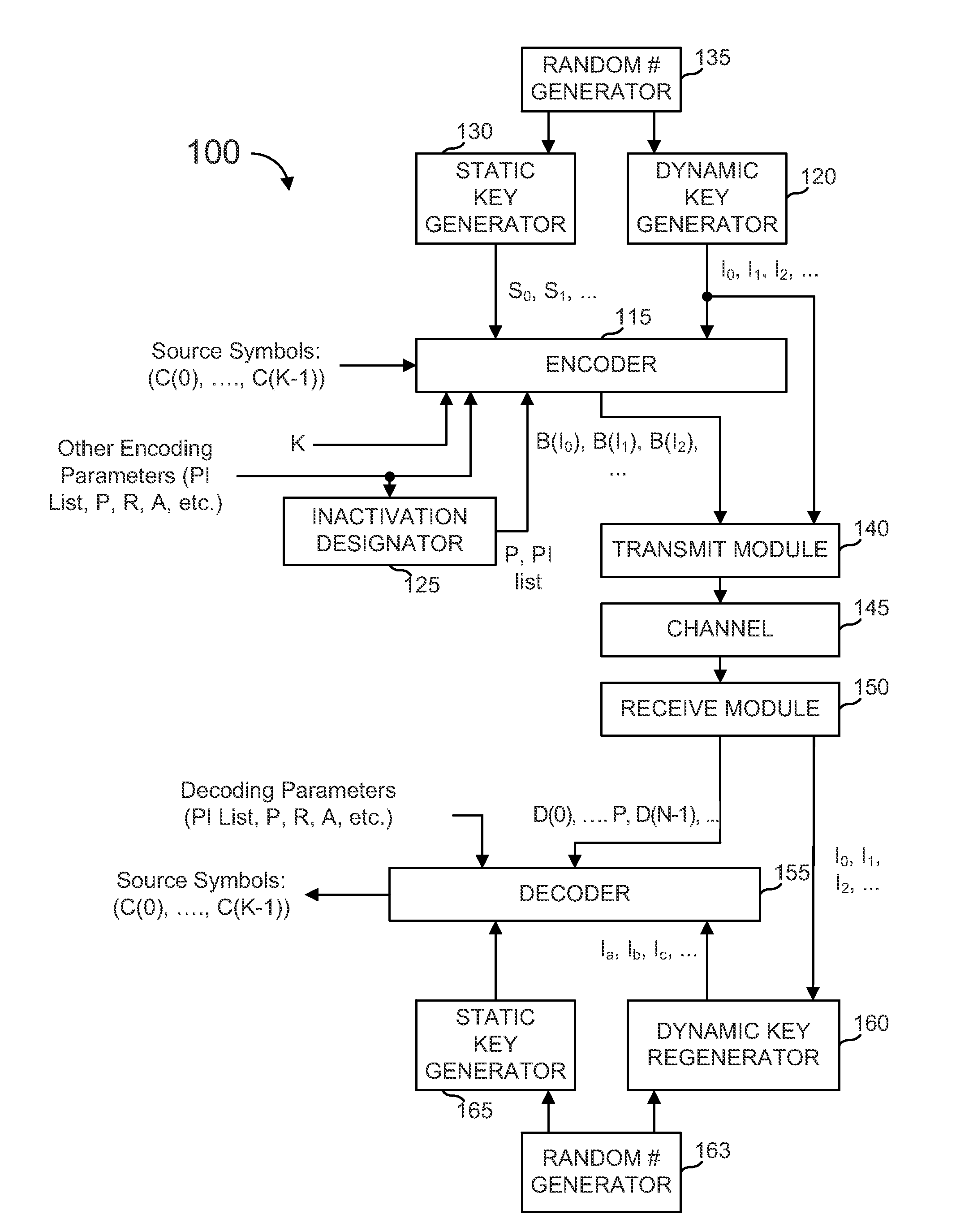
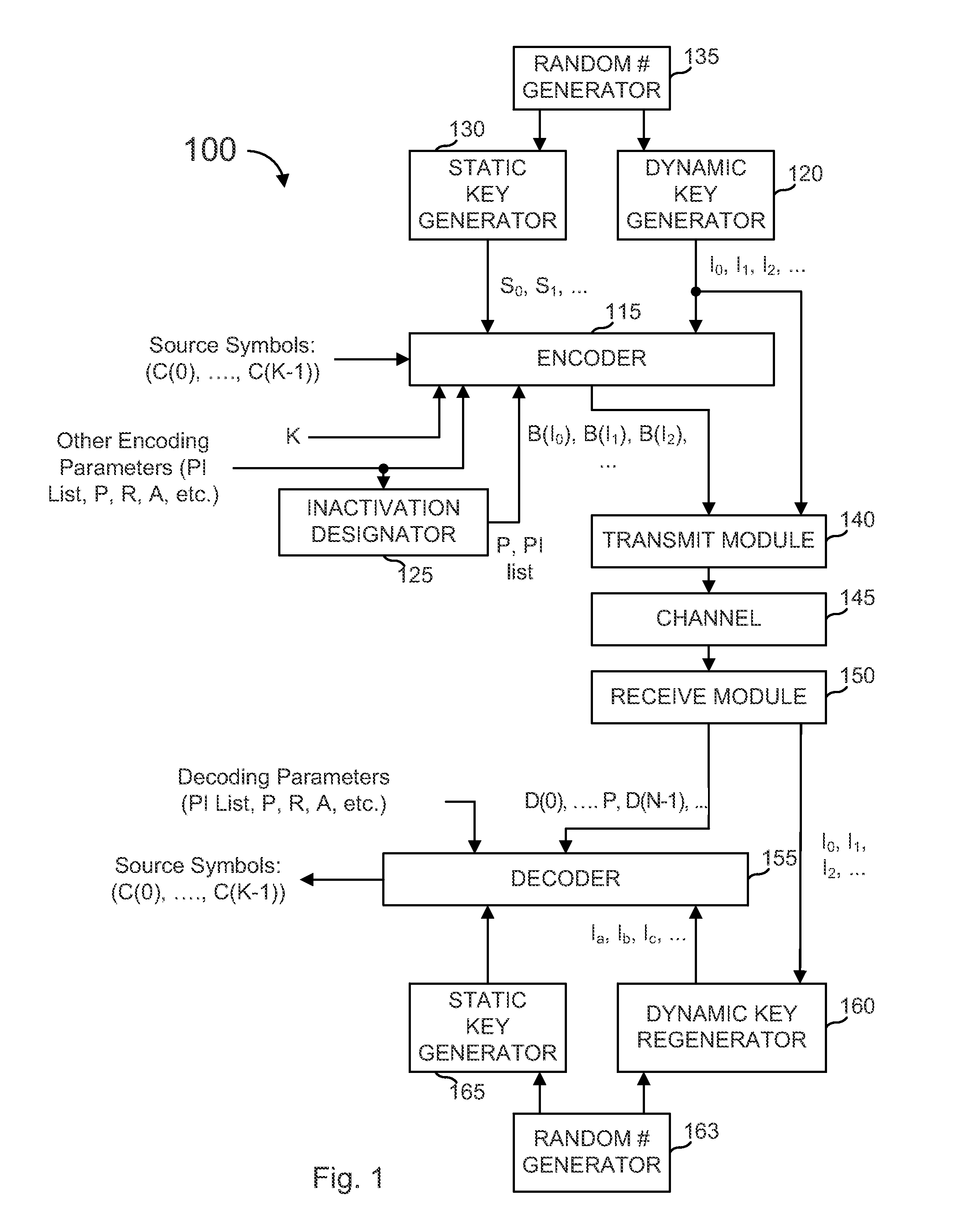
[0225]FIG. 30 illustrates an example encoding system 1000, that might be implemented as hardware modules, software modules, or portions of program code stored in a program store 1002 and executed by a processor 1004, possibly as a collective unit of code not separated as shown in the figure. Encoding system 1000 receives a signal in, conveying source symbols and parameter information, and outputs a signal conveying that information.

[0226]An input interface 1006 stores the incoming source symbols into a source symbol buffer 1008. A source-to-intermediate symbol generator 1010 generates intermediate symbols from the source symbols. This can be a pass-through in some embodiments and a decoder module in other embodiments (such as a “s...

example 1

[0299]Inputs:[0300]SS=5[0301]Al=4 bytes[0302](Min sub-symbol size=20 bytes)[0303]WS=128 KB=131,072 bytes[0304]P′=1,240 bytes[0305]F=6 MB=6,291,456 bytes

[0306]Calculations:[0307]T=1,240 bytes[0308]Kt=5,074[0309]N_max=62[0310]KL(N_max)=6,553[0311]Z=1[0312]KL=ceil(Kt / Z)=5,074[0313]N=52 (KL(N)=5,461)[0314]TL=6, larger sub-symbol=24 bytes[0315]TS=5, smaller sub-symbol=20 bytes[0316]TL*AL*KL=121,776

example 2

[0317]Inputs:[0318]SS=8[0319]Al=4 bytes[0320](Min sub-symbol size=32 bytes)[0321]WS=128 KB=131,072 bytes[0322]P′=1 KB=1,024 bytes[0323]F=56,404 KB=57,757,696 bytes

[0324]Calculations:[0325]T 32 1,024 bytes[0326]Kt=56,404[0327]N_max=32[0328]KL(N_max)=4,096[0329]Z=14[0330]KL=ceil(Kt / Z)=4,029[0331]N=32 (KL(N)=4,096)[0332]TL=8, larger sub-symbol=32 bytes[0333]TS=8, smaller sub-symbol=32 bytes[0334]TL*AL*KL=128,928

[0335]There are many variants of the above methods. For example, for some FEC code it is desirable to have at least a minimum number of source symbols in a source block to minimize the source block reception overhead of the FEC code. Since for really small file sizes or data block sizes F the size of the source symbol might become too small, there might also be a maximum number of source symbols into which a packet is partitioned. For example, in IETF RFC 5053, the desired minimal number of source symbols in a source block is Kmin=1024 and the maximum number of source symbols in...


PUM


Abstract

Encoding of a plurality of encoded symbols is provided wherein an encoded symbol is generated from a combination of a first symbol generated from a first set of intermediate symbols and a second symbol generated from a second set of intermediate symbols, each set having at least one different coding parameter, wherein the intermediate symbols are generated based on the set of source symbols. A method of decoding data is also provided, wherein a set of intermediate symbols is decoded from a set of received encoded symbols, the intermediate symbols organized into a first and second sets of symbols for decoding, wherein intermediate symbols in the second set are permanently inactivated for the purpose of scheduling the decoding process to recover the intermediate symbols from the encoded symbols, wherein at least some of the source symbols are recovered from the decoded set of intermediate symbols.

Description

CROSS REFERENCES[0001]This application is a continuation-in-part of U.S. patent application Ser. No. 12 / 604,773, filed Oct. 23, 2009, naming M. Amin Shokrollahi, et al. and entitled “Method and Apparatus Employing FEC Codes with Permanent Inactivation of Symbols for Encoding and Decoding Processes” and further claims priority from the following provisional applications, each naming M. Amin Shokrollahi, et al. and each entitled “Method and Apparatus Employing FEC Codes with Permanent Inactivation of Symbols for Encoding and Decoding Processes”: U.S. Provisional Patent Application No. 61 / 353,910, filed Jun. 11, 2010, U.S. Provisional Patent Application No. 61 / 257,146, filed Nov. 2, 2009, and U.S. Provisional Patent Application No. 61 / 235,285, filed Aug. 19, 2009. Each provisional and nonprovisional application cited above is hereby incorporated by reference for all purposes.[0002]The following references are herein incorporated by reference in their entirety for all purposes:[0003]1) ...

Claims


Application Information

Patent Timeline
Patent Type & Authority Applications(United States)
IPC IPC(8): H04L27/04H04L27/06
CPCH03M13/3761H04L1/0066H04L1/0065H04L1/0041H03M13/37H03M13/458H04L1/0064
Inventor LUBY, MICHAEL G.SHOKROLLAHI, MOHAMMAD AMINMINDER, LORENZ CHRISTOPH
Owner QUALCOMM INC
Why Eureka
Try Eureka