Central Vacuum Cooling Plant

a vacuum cooling and vacuum pump technology, applied in food preservation, packaging under special atmospheric conditions, food science, etc., can solve the problems of higher energy consumption than theoretically necessary, undersize two-stage vacuum pumps, etc., and achieve energy saving, net power saving, and efficient vacuum draw

Active Publication Date: 2011-12-08
F L SMIDTH & CO AS
View PDF5 Cites 8 Cited by
  • Summary
  • Abstract
  • Description
  • Claims
  • Application Information

AI Technical Summary

Benefits of technology

[0006]Hereby is obtained a significant energy saving, which mainly is caused by splitting up the pressure lowering and maintaining steps into at least two, and more preferably three, distinct phases in which specifically sized vacuum pumps are used to most efficiently draw the required vacuum during the cooling process. Thus, in a three step plant a single stage vacuum pump may used for the first, fast pressure lowering step in which the pressure is lowered down to approximately −25″ Hg (gage) point. In the second, the pressure is lowered from the intermediate pressure of approximately −25″ Hg (gage) to a minimum or “bounce” point (typically about 4.5 mm Hg absolute pressure) using a medium, typically two stage vacuum pump. In the third step, minimum power consumption is needed to maintain vacuum level at the bounce point in the retort. In this step, typically but not always the longest part of the overall cooling cycle, the bounce point is maintai

Problems solved by technology

Often the two stage vacuum pumps used are somewhat undersized for the first pressure lowering step, but oversized for the second pressure maintaining step.
This entails higher energy consumption than theoretical necessary,

Method used


Image

  • Central Vacuum Cooling Plant
  • Central Vacuum Cooling Plant
  • Central Vacuum Cooling Plant

Examples


Embodiment Construction

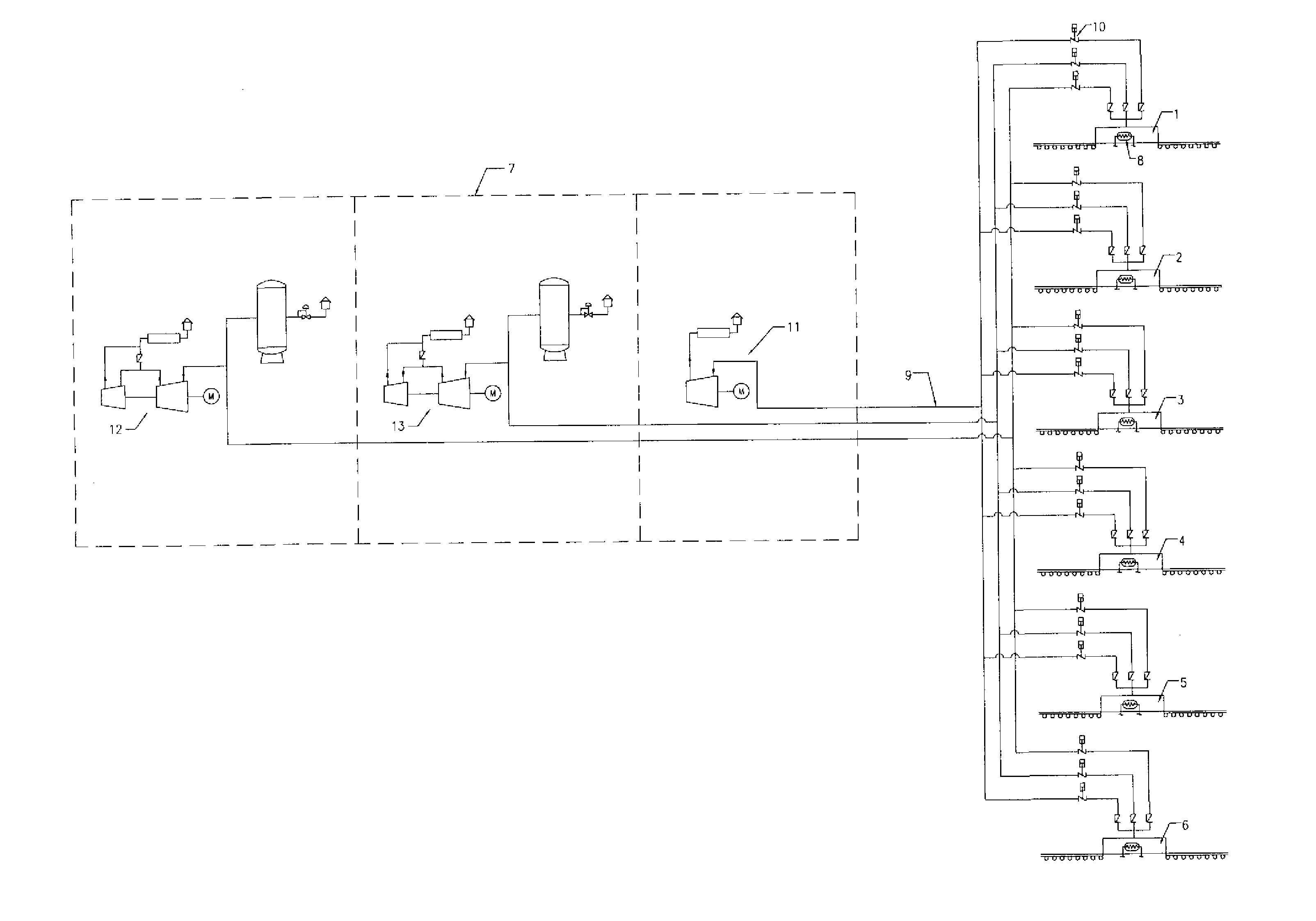
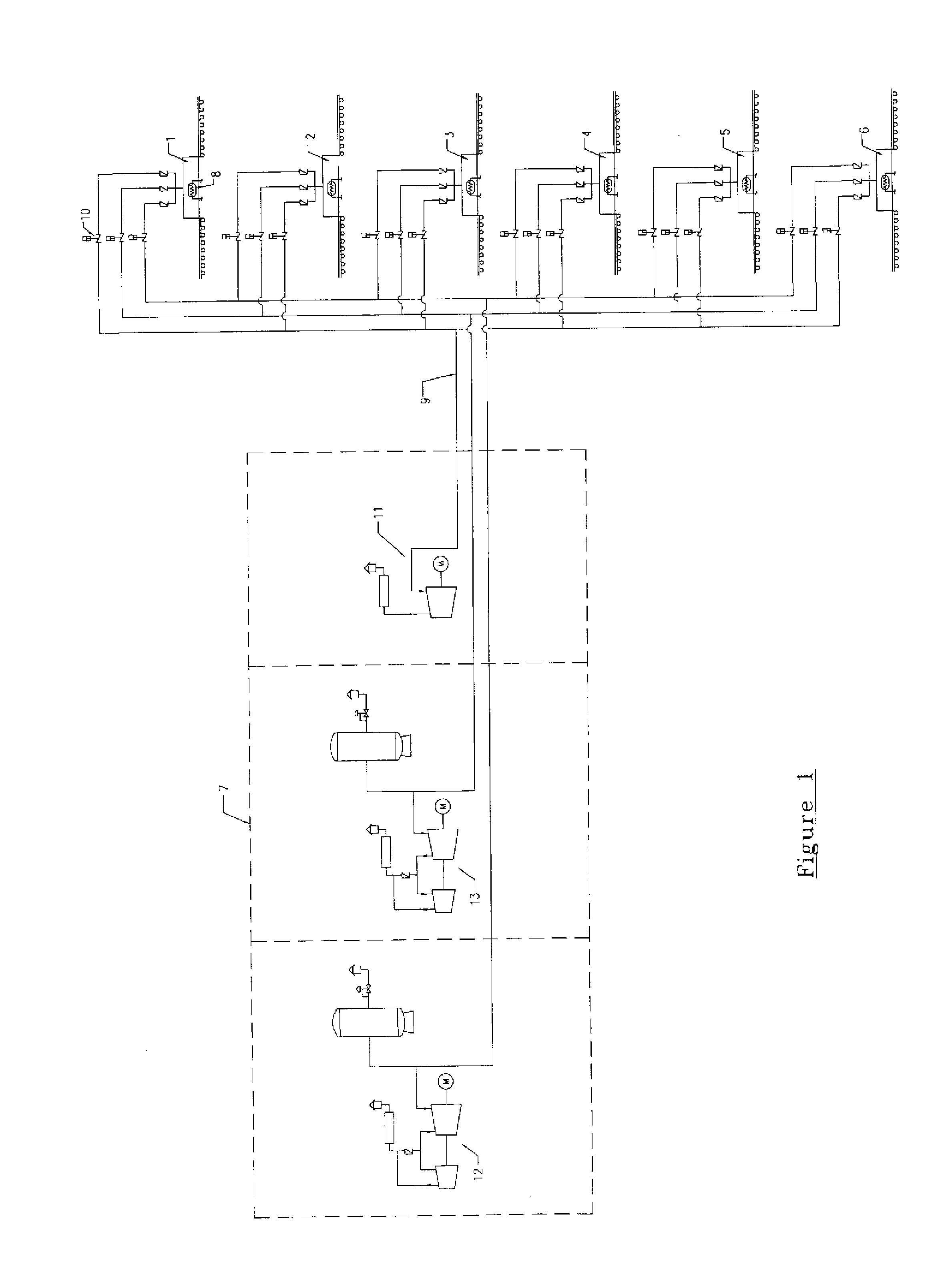
[0004]This object is obtained by a method according to the introduction, one embodiment of which being that the steps in the process of lowering and maintaining the pressure at the desired level are achieved using at least two, and most preferably three, separate vacuum pumps—typically one for each step.

[0005]In the present invention the initial step of lowering the pressure inside the vacuum chamber to the predetermined minimum pressure level is carried out using a single stage vacuum pump and the step of maintaining the vacuum chamber at this predetermined minimum pressure level is carried out using a two stage vacuum pump.

[0006]Hereby is obtained a significant energy saving, which mainly is caused by splitting up the pressure lowering and maintaining steps into at least two, and more preferably three, distinct phases in which specifically sized vacuum pumps are used to most efficiently draw the required vacuum during the cooling process. Thus, in a three step plant a single stage...


PUM


Abstract

Described is a method as well as an apparatus for vacuum cooling of food produce through moisture removal, which method comprising the steps of loading the food produce to be cooled into a vacuum chamber, lowering the pressure inside the vacuum chamber to a predetermined pressure level and maintaining the vacuum chamber at this predetermined pressure level both by removing air through a vacuum pump system for a sufficient of time to allow heat transfer out of the food produce to take place, and condensing water vapor inside the vacuum chamber through a refrigeration system. The method and apparatus is unique in that the step of lowering the pressure inside the vacuum chamber to the predetermined pressure level is carried out using a single stage vacuum pump and the step of maintaining the vacuum chamber at this predetermined pressure level is carried out using a two stage vacuum pump.
There is obtained a significant energy saving, which mainly is caused by splitting up the pressure lowering and maintaining steps into two distinct phases in which specifically sized vacuum pumps are used to most efficiently draw the required vacuum during the cooling process. Thus, the single stage vacuum pump used for the pressure lowering step has no high pressure stage that is idling during this step, meaning there is a net power saving or alternatively an increase in performance. Further, the two stage vacuum pump maintaining the pressure in the vacuum chamber for the required duration may be very small having very low displacement and thus low power consumption. In addition, splitting up the pressure lowering and maintaining steps into two distinct phases makes it possible to operate more vacuum chambers simultaneously in any combination, i.e. where some vacuum chambers are in the pressure lowering step others may be in the pressure maintaining step.

Description

[0001]The present invention relates to a method for vacuum cooling of produce through moisture removal, which method comprising the steps of loading the produce to be cooled into a vacuum chamber, also know as a “retort”, lowering the pressure inside the vacuum chamber to a predetermined pressure level and maintaining the vacuum chamber at this predetermined pressure level both by removing air through a vacuum pump system for a sufficient of time to allow heat transfer out of the produce to take place, and condensing water vapor inside the vacuum chamber through a refrigeration system. This may be done in a two or more, and preferable a three, step process typically utilizing separate vacuum pumps in each step. Further, the invention relates to a vacuum cooling apparatus.BACKGROUND OF THE INVENTION[0002]Vacuum cooling is a well known and proven cooling method within the fresh food produce industry. The method is widely used for cooling fresh produce from temperatures of up to about ...

Claims


Application Information

Patent Timeline
IPC IPC(8): B65D81/20A23B7/02A23L3/36
CPCA23L3/36Y02P60/85
Inventor SCHWARTZ, LOUIS
Owner F L SMIDTH & CO AS
Why Eureka
Try Eureka