High efficiency piezoelectric micro-generator and energy storage system

Inactive Publication Date: 2011-12-15
SIRIUS IMPLANTABLE SYST
View PDF3 Cites 48 Cited by
  • Summary
  • Abstract
  • Description
  • Claims
  • Application Information

AI Technical Summary

Benefits of technology

[0039]It is a core purpose of the invention to provide the step of picking up mechanical energy performed by the piezoelectric elemen

Problems solved by technology

Most implantable devices contain primary batteries which have a limited lifetime, contain act

Method used


Image

  • High efficiency piezoelectric micro-generator and energy storage system
  • High efficiency piezoelectric micro-generator and energy storage system
  • High efficiency piezoelectric micro-generator and energy storage system

Examples


Example

[0057]The following description is provided, alongside all chapters of the present invention, so as to enable any person skilled in the art to make use of said invention and sets forth the best modes contemplated by the inventor of carrying out this invention. Various modifications, however, are adapted to remain apparent to those skilled in the art, since the generic principles of the present invention have been defined specifically to provide a piezoelectric micro-generator.

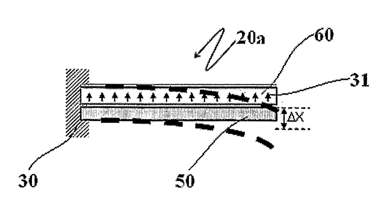
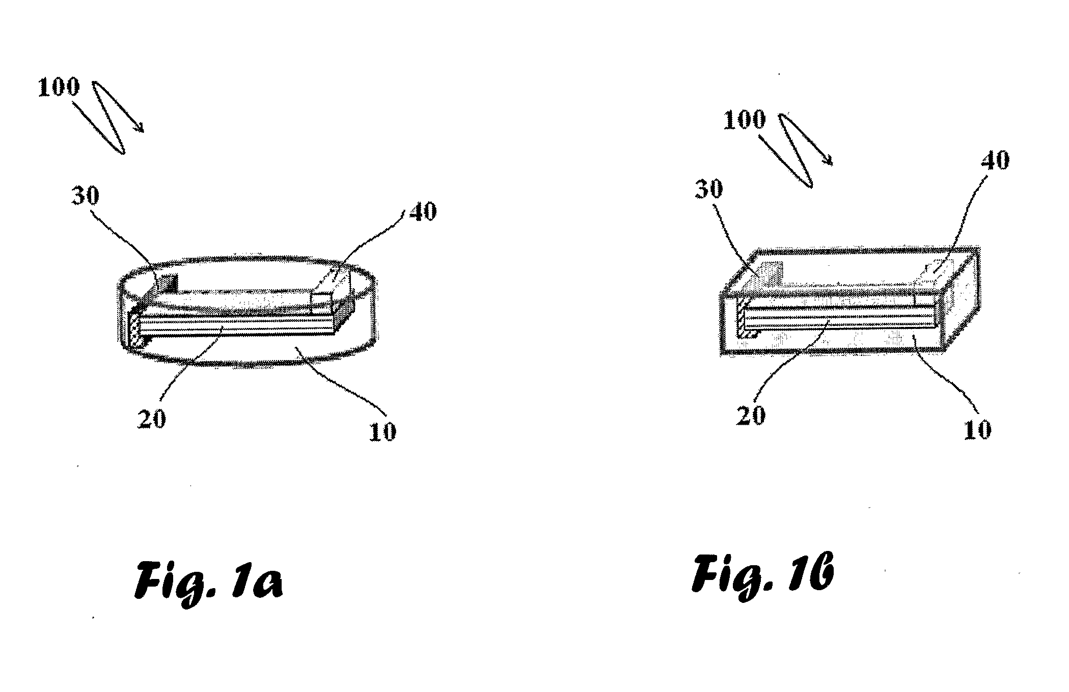
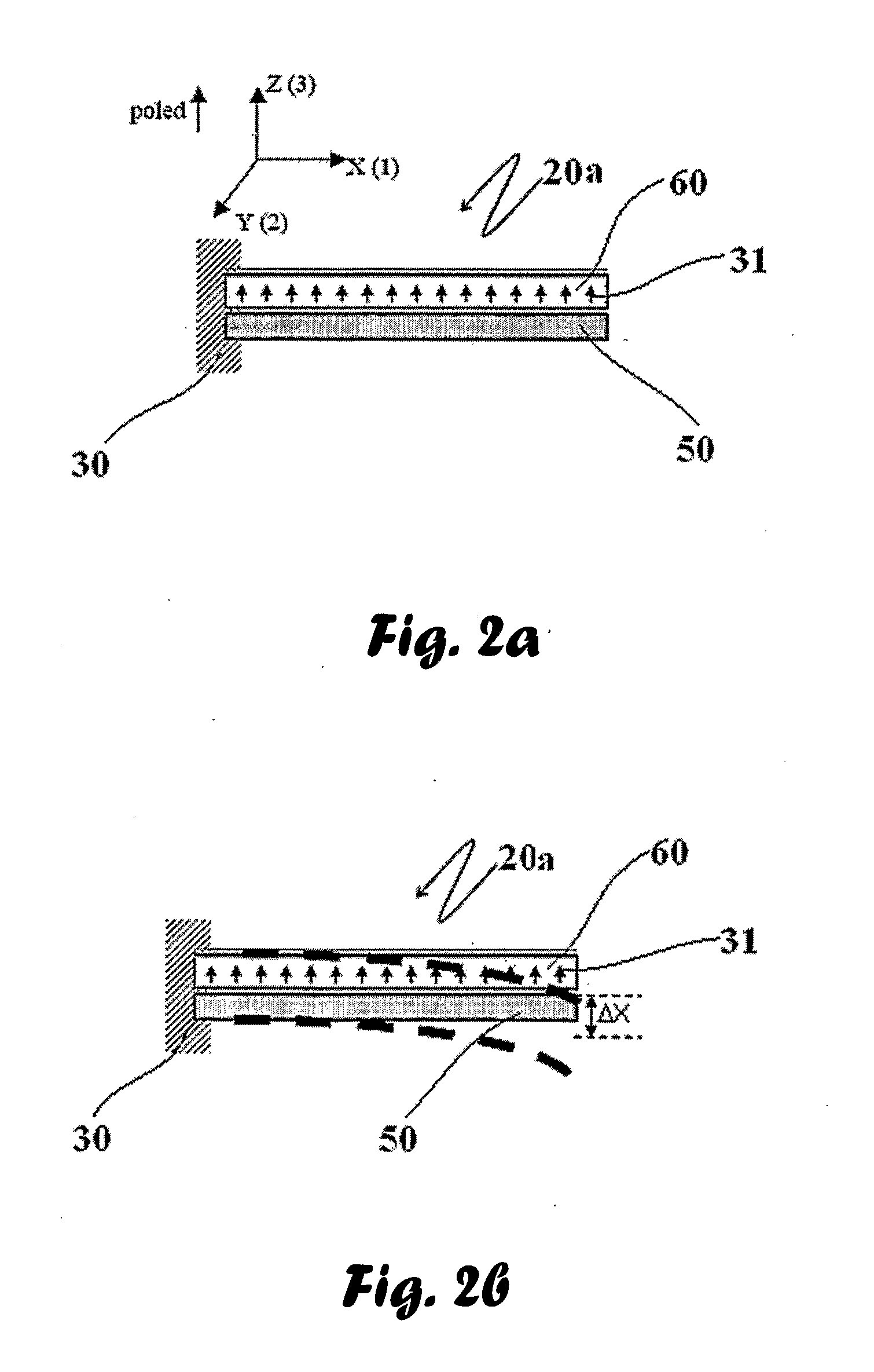
[0058]The components comprising the piezoelectric micro-generator device include: (a) Enclosure—can anchored to the moving body and including the parts comprising the micro-generator. (b) Harnessing mechanism—mechanism trapping and transforming the motion of the enclosure to impart deflection / deformation to the piezoelectric element; (c) piezoelectric element—element converting the mechanical motion of displacement / distortion to electrical energy; (d) charging power management—unit rectifying the AC output of t...


PUM


Abstract

This present invention provides a power supply for implanting into a patient's body and providing electricity to a load within the body, said power supply comprising an enclosure; adapted for optimizing an activating force by mechanisms of orienting thereof; the power supply further comprising (a) a piezoelectric micro-generator comprising (b) electrical energy storing means; (c) control unit adapted for managing charging and discharging said storing means said control unit further provided with means for decoupling said piezoelectric element from and connecting to said electrical energy storing means to increase efficiency of said power supply.

Description

FIELD OF INVENTION[0001]The invention relates to a method for making a self-contained renewable power source comprising a power generation unit harnessing external motion and exploiting the corresponding mechanical energy to generate electrical energy, an energy management unit that rectifies the generated AC electrical energy and manages its storage and utilization, and a specialized energy storing element which stores the energy and delivers it subsequently, upon demand.[0002]Components comprising the micro-generator unit are contained within a preferably hermetically sealed enclosure attached, anchored or secured to a moving body that imparts the motion to the enclosure and consequently to the motion harnessing element and the contained piezoelectric element. The enclosure containing the piezoelectric element and the motion harnessing element, constituting a part of the invented device, is set in motion by implanting and affixing the invented device to a moving body like a heart,...

Claims


Application Information

Patent Timeline
IPC IPC(8): H02N2/18H01L41/113
CPCA61N1/3785A61N1/3787H02N2/188H02N2/181H01L41/1136H10N30/306
Inventor MEITAV, ARIEHGELVAN, DAN
Owner SIRIUS IMPLANTABLE SYST
Why Eureka
Try Eureka