
Battery assembly for battery powered portable devices

a portable computing and battery technology, applied in the direction of wound/folded electrode electrodes, instruments, secondary cell details, etc., can solve the problems of reducing the energy density per mass, complex tradeoffs in the design of portable computing devices, and adverse effects on one of more other design factors

Active Publication Date: 2011-12-15
APPLE INC
View PDF4 Cites 9 Cited by
  • Summary
  • Abstract
  • Description
  • Claims
  • Application Information

AI Technical Summary

Benefits of technology

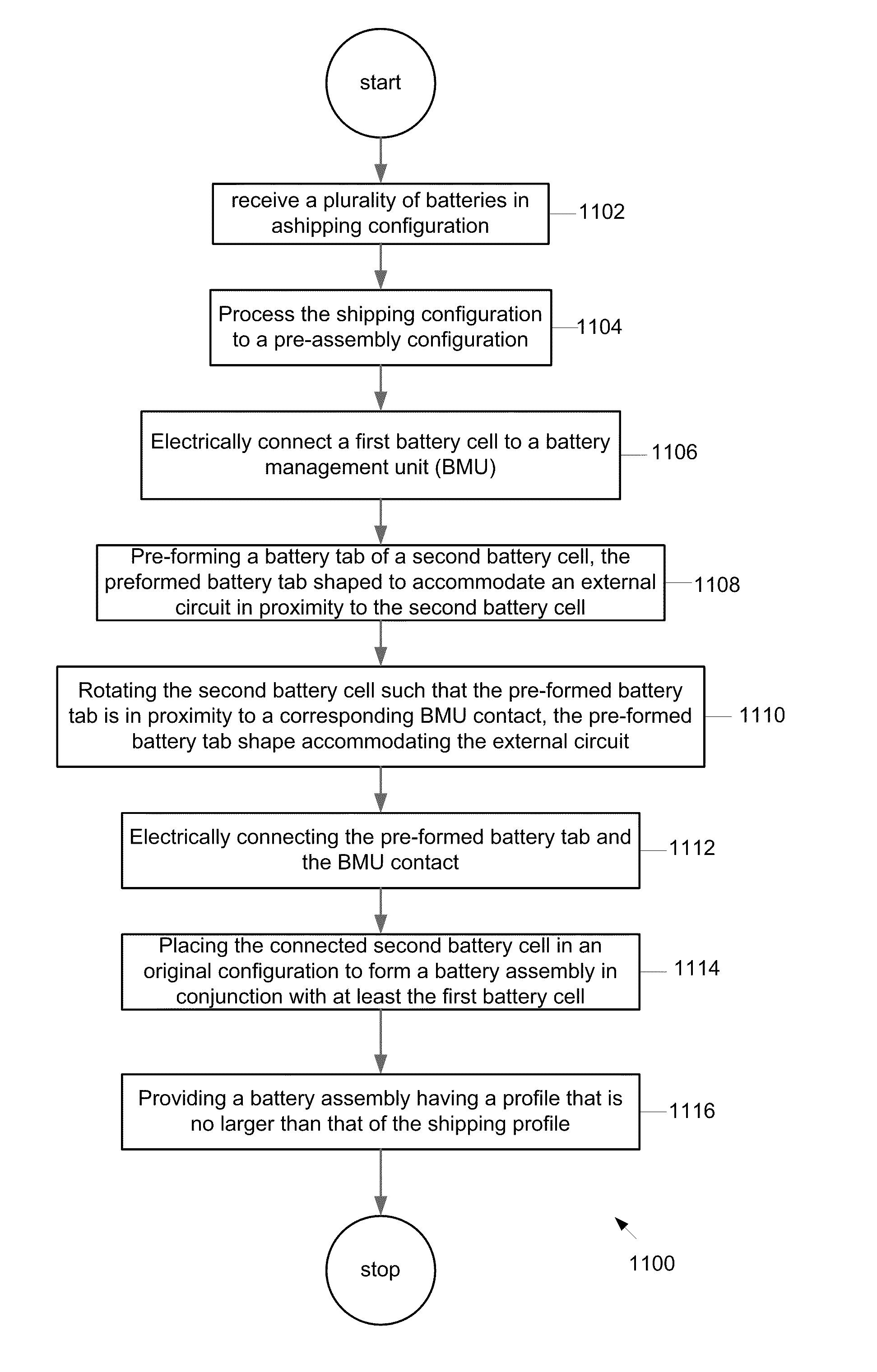
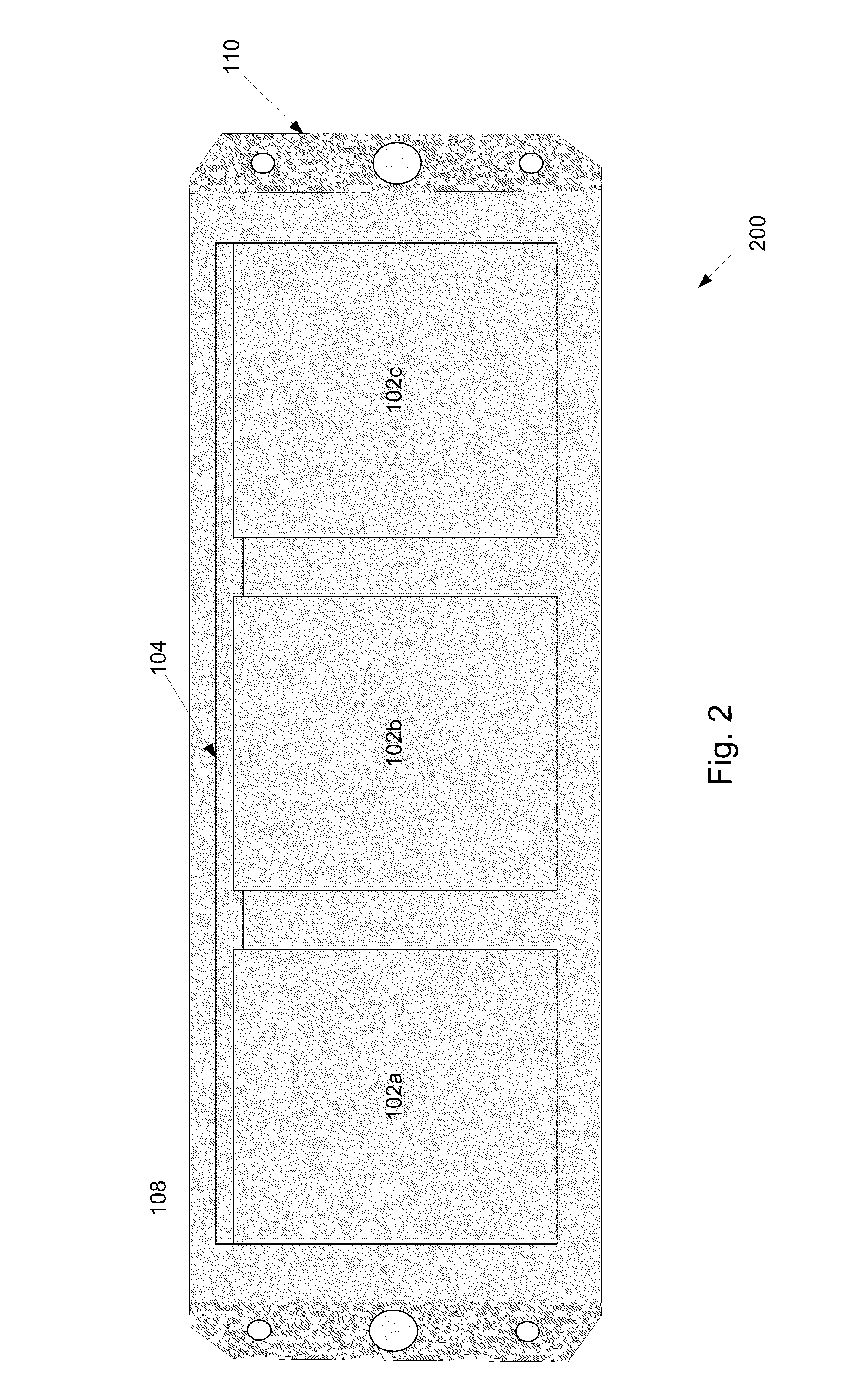
[0011]A battery assembly includes at least a plurality of battery cells each of which includes at least an electrode assembly including an anode and a cathode, and an electrolyte, and a containment structure for enclosing the electrode and the electrolyte, the containment structure configured to prevent leakage of the electrolyte or gasses generated during operation of the battery assembly. The plurality of battery cells includes at least a first and a second battery cell each attached to a distributed battery monitoring unit, the second battery cell being associated with an external circuit, the second battery cell connected to a battery management unit (BMU) by way of a pre-formed battery contact shaped to accommodate the external circuit. The plurality of battery cells are electrically connected to at least the BMU such that each of the plurality of battery cells are substantially aligned with each other thereby preserving a battery profile corresponding to unconnected battery cells.

Problems solved by technology

A design of a portable computing device can involve complex tradeoffs.
A component that is selected on the basis of its positive contribution to one of these design factors can have an adverse impact on one of more other design factors.
First, the energy density per mass will decrease as the mass of the packaging increases.
An inefficiently packaged battery cell can have a lower energy density per volume than an efficiently packaged battery cell.
As the energy density per volume decreases, the volume taken up by the portable power device increases, which can be undesirable for utilization with a portable computing device.

Method used


Image

  • Battery assembly for battery powered portable devices
  • Battery assembly for battery powered portable devices
  • Battery assembly for battery powered portable devices

Examples


Embodiment Construction

[0002]The described embodiments relate generally to batteries for portable computing devices. More particularly, the present embodiments relate to conformally shaped battery packaging designs suitable for tablet devices.

DESCRIPTION OF THE RELATED ART

[0003]A design of a portable computing device can involve complex tradeoffs. A few factors that can be considered in the design process are cosmetic appeal, weight, manufacturability, durability, thermal compatibility and power consumption. A component that is selected on the basis of its positive contribution to one of these design factors can have an adverse impact on one of more other design factors.

[0004]A portable power source, typically, a battery of some type is an important component in the design of a portable computing device. The portable power source provides operating power for the portable computing device when it is not near a fixed power source, such as a wall outlet. Factors in selecting a portable power source can be en...


PUM

PropertyMeasurementUnit
shapeaaaaaaaaaa
sizeaaaaaaaaaa
durabilityaaaaaaaaaa

Abstract

A battery assembly includes at least a plurality of battery cells that includes at least a first and a second battery cell each attached to a distributed battery monitoring unit, the second battery cell being associated with an external circuit, the second battery cell connected to a battery management unit (BMU) by way of a pre-formed battery contact shaped to accommodate the external circuit. The plurality of battery cells are electrically connected to at least the BMU such that each of the plurality of battery cells are substantially aligned with each other thereby preserving a battery profile corresponding to unconnected battery cells.

Description

CROSS REFERENCE TO RELATED APPLICATIONS[0001]This patent application takes priority under 35 U.S.C. 119(e) of U.S. Provisional Patent Application entitled “BATTERY ASSEMBLY FOR TABLET LIKE DEVICES” by McClure et al. filed Jun. 14, 2010 that is incorporated by reference in its entirety for all purposes.FIELD OF THE DESCRIBED EMBODIMENTS[0002]The described embodiments relate generally to batteries for portable computing devices. More particularly, the present embodiments relate to conformally shaped battery packaging designs suitable for tablet devices.DESCRIPTION OF THE RELATED ART[0003]A design of a portable computing device can involve complex tradeoffs. A few factors that can be considered in the design process are cosmetic appeal, weight, manufacturability, durability, thermal compatibility and power consumption. A component that is selected on the basis of its positive contribution to one of these design factors can have an adverse impact on one of more other design factors.[000...

Claims


Application Information

Patent Timeline
Patent Type & Authority Applications(United States)
IPC IPC(8): H05K7/14H01M10/02H01R43/20H01M50/209H01M50/247H01M50/569
CPCG06F1/1626G06F1/1635H01M2/0207H01M2/1066H01M2/204H01M2/34Y10T29/49208H01M10/0565H01M10/46H01M2/1022Y10T29/49108Y10T29/53135H01M10/0431Y02E60/10H01M50/209Y02P70/50H01M10/482H01M50/247H01M50/569H01M10/0436H01M10/425H01M50/284H01M2010/4271
Inventor MCCLURE, STEPHEN R.HAGADONE, SCOTT J.DEVAN, SHEBAVALENTINE, VAL
Owner APPLE INC
Learn More