
Method for impregnating a porous body by a suspension and installation for implementing same

a porous body and suspension technology, applied in the field of monolithic honeycomb bodies, can solve the problems of significant increase in pressure drop, harmful discharge to man's health, and injurious to health

Inactive Publication Date: 2011-12-15
INST FR DU PETROLE +1
View PDF1 Cites 19 Cited by
  • Summary
  • Abstract
  • Description
  • Claims
  • Application Information

AI Technical Summary

Benefits of technology

[0038]The DV90 / Dpores ratio defined in the present invention is strictly positive. It can be preferably above 0.001, more preferably above 0.01.

Problems solved by technology

The exhaust gas of diesel type internal-combustion engines generally comprises particles or soots that are discharged into the atmosphere and such discharge is harmful to man's health.
This gas also contains other pollutants such as carbon oxides CO, nitrogen oxides NOx (nitrogen monoxide NO and nitrogen dioxide NO2) and unburnt hydrocarbons, which are discharged into the atmosphere without being treated and are therefore also injurious to health.
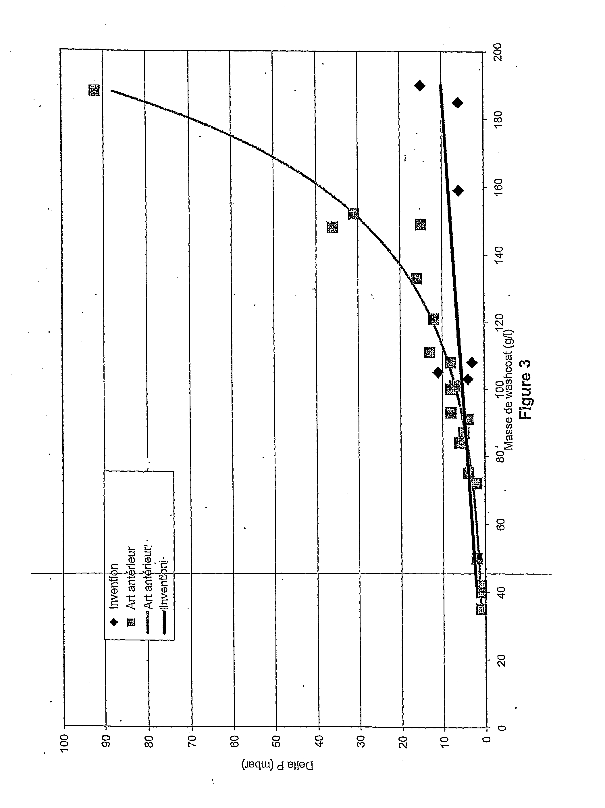
This has the disadvantage of significantly increasing pressure drops when the amount of deposited washcoat is large.
The amount of washcoat deposited within the pores by means of these methods is however low, or even insufficient, or it requires many successive deposition operations.
This has the drawback of complicating the impregnation process and of requiring a membrane.

Method used


Image

  • Method for impregnating a porous body by a suspension and installation for implementing same
  • Method for impregnating a porous body by a suspension and installation for implementing same
  • Method for impregnating a porous body by a suspension and installation for implementing same

Examples


Embodiment Construction

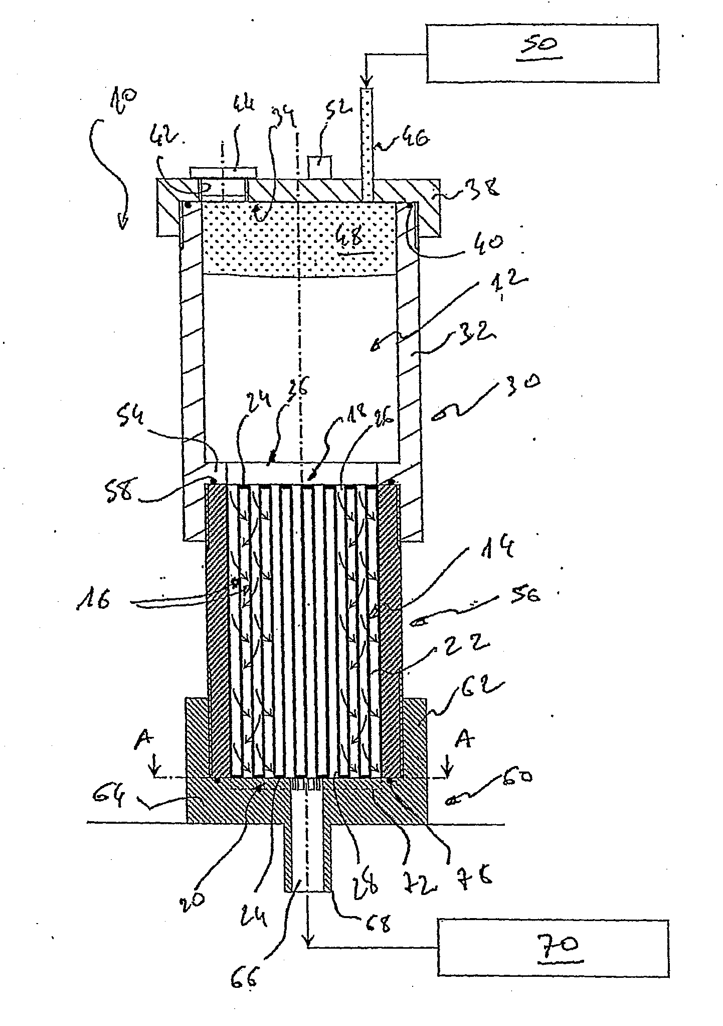
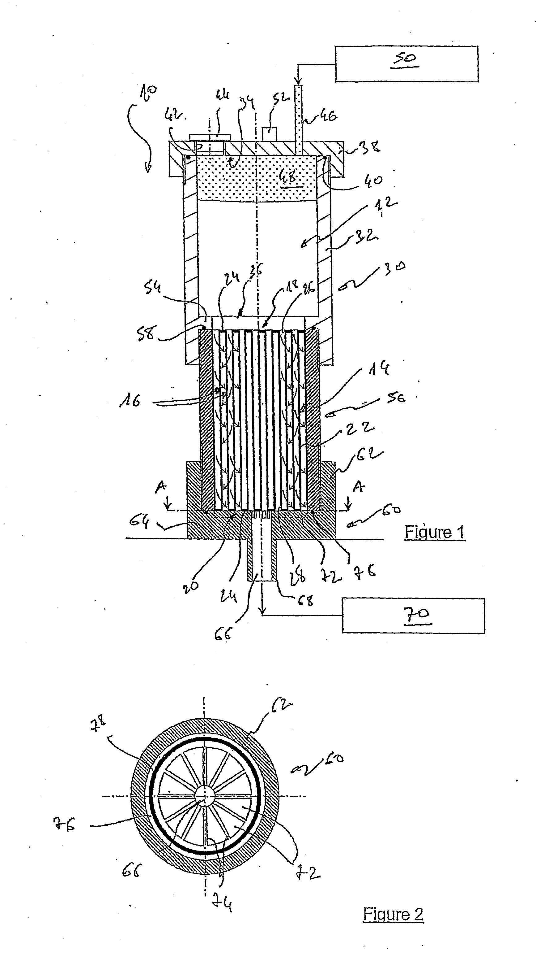
[0043]FIG. 1 shows an installation 10 for impregnating a porous body 14 by a suspension 12.

[0044]In the example shown, body 14 preferably is a monolithic honeycomb ceramic body. The ceramic material can be silicon carbide, silicon nitride, cordierite, mullite, sialon, boron nitride, silica, alumina, aluminosilicates, aluminium titanate or zirconium phosphate, and it can concern a pure (single ceramic composition) or composite (several different ceramic compositions) ceramic material.

[0045]This body comprises a multiplicity of substantially parallel channels 16 extending from an end face 18 of this body to another end face 20. These channels are separated from one another by porous walls 22 and their section can have any desired shape (circular, square, rectangular, triangular, etc.). These channels comprise plugs 24 at one or at the other end thereof so as to form inlet 26 and outlet 28 channels. The inlet channels comprise open ends at the level of face 18 and blocked ends at the l...


PUM

PropertyMeasurementUnit
pore size distributionaaaaaaaaaa

Abstract

The present invention relates to a method for impregnating a porous body (14) by a suspension (12) containing at least partly particles, said body comprising a multiplicity of channels (16) delimited by porous walls (22) extending from one (18) of the faces to the other (20) face of said body, part of said channels being obstructed at one face and the other part of the channels being obstructed at the other face.According to the invention, the method consists in:making a suspension whose particle size distribution meets a DV90 / Dpores ratio below 0.25 and whose viscosity is such that said suspension is brought inside the walls while depositing part of the particles on the surface of the pores of the walls,communicating one (18, 20) of the faces of body (14) with an enclosure (30) containing the suspension,feeding the suspension into the body,exerting a force on the suspension introduced so that said suspension flows through the walls,passing a fluid through the walls.

Description

FIELD OF THE INVENTION[0001]The present invention relates to a method for impregnating a porous body with a suspension, in particular a monolithic honeycomb body, and to an installation for using same.[0002]It more particularly relates to a monolith made of a porous ceramic material used for filtration of a gas stream or a liquid stream.[0003]The invention especially but not exclusively aims at a method for coating a porous body used as a Particle Filter (PF) for the exhaust gas of an internal-combustion engine, notably of diesel type.BACKGROUND OF THE INVENTION[0004]The exhaust gas of diesel type internal-combustion engines generally comprises particles or soots that are discharged into the atmosphere and such discharge is harmful to man's health. This gas also contains other pollutants such as carbon oxides CO, nitrogen oxides NOx (nitrogen monoxide NO and nitrogen dioxide NO2) and unburnt hydrocarbons, which are discharged into the atmosphere without being treated and are therefo...

Claims


Application Information

Patent Timeline
Patent Type & Authority Applications(United States)
IPC IPC(8): B01D39/00B05D7/00B01D53/86B05C11/00B01D46/00B01D37/00B05D5/00B05C9/02
CPCB01D53/945Y02T10/22B01D2255/1023B01D2255/1025B01D2255/2042B01D2255/2092B01D2255/407B01D2279/30B01J23/63B01J35/023B01J35/04B01J37/0201B01J37/0205B01J37/0211B01J37/0215B01J37/0234B01J37/0242B01D2255/1021Y02T10/12B01J35/56B01J35/40
Inventor LAMBERT, ARNOLDLEMINTER, PHILIPPEBECUE, THIERRYJOULIN, JEAN-PIERRECARTOIXA, BRUNO
Owner INST FR DU PETROLE
Learn More