
Apparatus for production of metallic slab using electron beam, and process for production of metallic slab using the apparatus

a technology of electron beam and apparatus, which is applied in the field of electrochemical melting technique of metal, can solve the problems of difficult to adapt the technique the inability of titanium metal when heated to contact air, and the inability to increase the width of the slab in the field of continuous casting of steel, etc., to achieve the effect of reducing pressure or vacuum in the metal melting part, easy variation, and reducing pressure or vacuum

Inactive Publication Date: 2011-12-22
TOHO TITANIUM CO LTD +1
View PDF15 Cites 7 Cited by
  • Summary
  • Abstract
  • Description
  • Claims
  • Application Information

AI Technical Summary

Benefits of technology

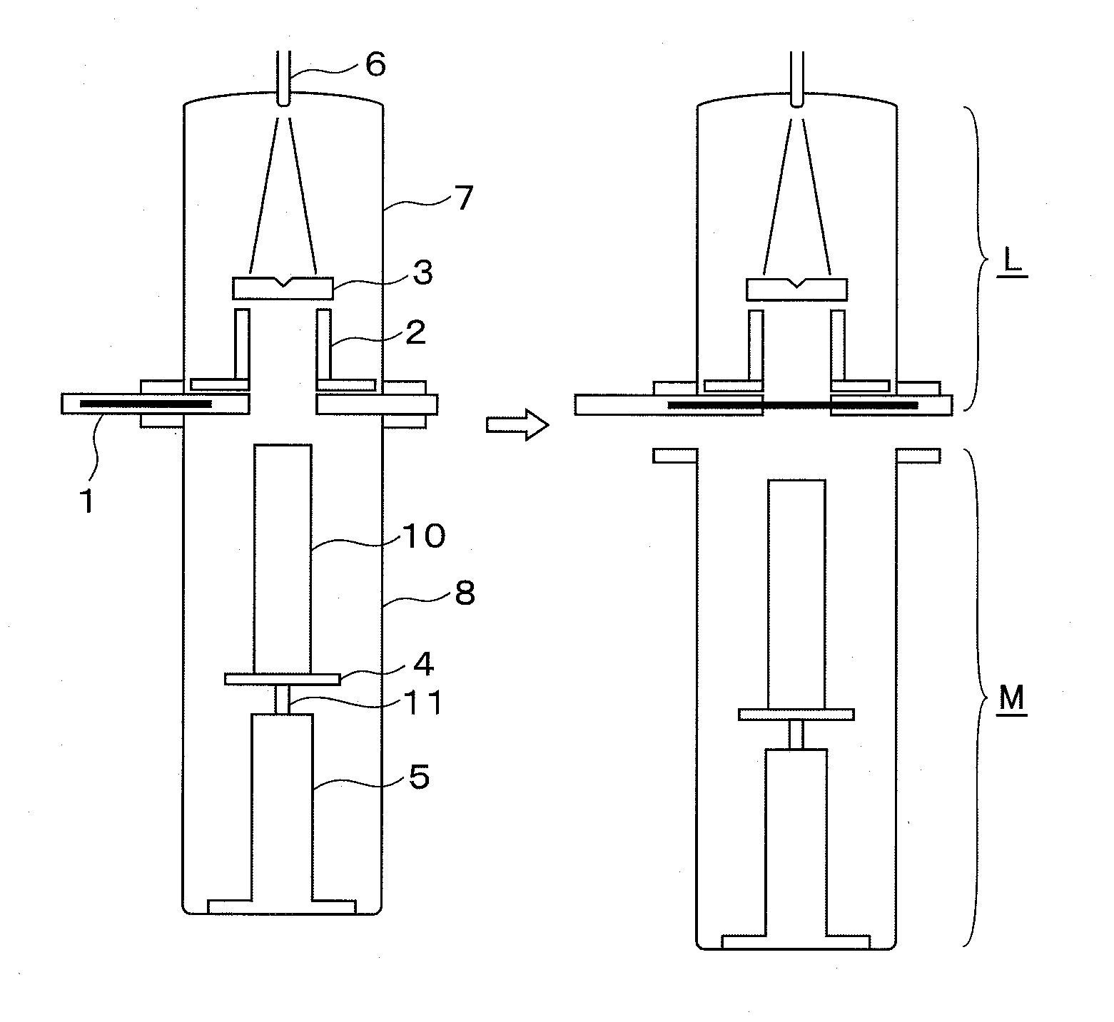
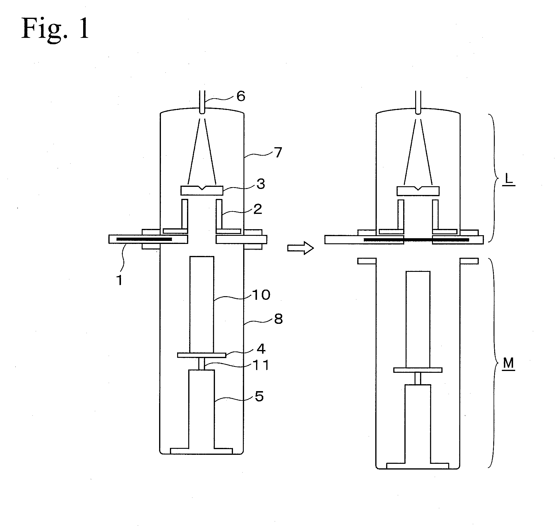
[0031]By using the apparatus and process for production of metallic slabs using the electron beam mentioned above, the slab can be pulled out from the rectangular mold to the part of extracting the metal slab while maintaining reduced pressure or a vacuum in the metal melting part. As a result, a width of the rectangular mold held in the metal melting part can be easily varied while maintaining reduced pressure or a vacuum, and slabs each having a different width can be produced efficiently.

Problems solved by technology

However, a technique in which the width of the slab is increased has not yet been made in the field of continuous casting of steel due to potential for breakout.
However, unlike steel, since titanium metal is reactive, titanium metal when heated cannot be allowed to contact air.
Therefore, it is difficult to adapt the techniques for continuous casting of steel as they are for the casting of titanium, and it is necessary that a titanium slab, which is pulled out of a mold, be held in a vacuum, separated from air, and be cooled.
Since these processes are complicated, it is necessary to improve these processes.

Method used


Image

  • Apparatus for production of metallic slab using electron beam, and process for production of metallic slab using the apparatus
  • Apparatus for production of metallic slab using electron beam, and process for production of metallic slab using the apparatus
  • Apparatus for production of metallic slab using electron beam, and process for production of metallic slab using the apparatus

Examples


first embodiment

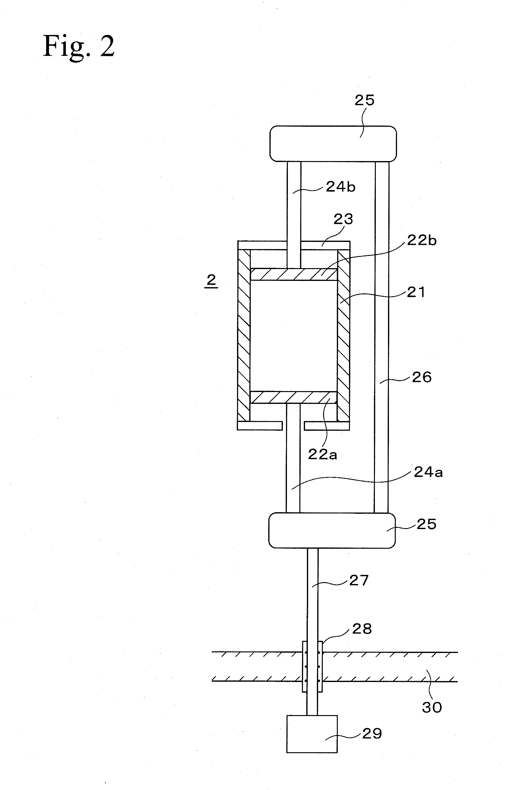
[0047]In the present invention, after the pullout operation of the metal slab 10, the width of the rectangular mold 2 arranged in the metal melting part L can be changed. FIG. 2 shows a desirable feature of the rectangular mold of variable wall distance 2 used in the process for production of metal ingot according to the first embodiment of the present invention. FIG. 2 is a diagram in which the rectangular mold 2 in FIG. 1 is seen from above.

[0048]The rectangular mold 2 in this embodiment is constructed by mold walls of a long side 21 and short mold walls 22a and 22b are mutually connected to wall driving shafts 24a and 24b each penetrating shaft guides 23. The wall driving shafts 24a / 24b are connected to each of shaft driving devices 25, and the shaft driving devices 25 are connected to each other by a power transmitting shaft 26. The shaft driving devices 25 are connected to a wall driving motor 29 arranged in the air which is outside of the electron beam melting furnace wall 30,...

second embodiment

[0064]FIG. 5 shows a desirable feature according to a second embodiment of the present invention. In this embodiment, the motor 29 which drives the short mold walls 22a and 22b is arranged inside of the electron beam melting furnace wall 30. As a result, it is not necessary to form a penetrating hole through which the motor driving axis 27 transmits motive power of the motor arranged outside of the furnace to the inside as in FIG. 4, on the furnace wall. Therefore, air is prevented from entering via the penetrating hole.

third embodiment

[0065]FIG. 6 shows a desirable feature according to third embodiment of the present invention. In this embodiment, two independent motors 29 separately drive the short mold walls 22a and 22b and are arranged outside of the short mold walls. As a result, alignment of the short mold walls of 22a and 22b can be promoted more accurately than in the cases of the first and second embodiments in which the driving force by one motor is dispersed to a pair of the short mold walls.


PUM

PropertyMeasurementUnit
Widthaaaaaaaaaa
Metallic bondaaaaaaaaaa
Distanceaaaaaaaaaa

Abstract

An apparatus and method allows the width of high-melting temperature reactive metallic slabs produced in an electron beam melting furnace to be easily changed. The apparatus for production of the metallic slabs by the electron beam melting has a metal melting part and a metal extraction part mutually separated by an air tight valve; a metal melting part has a melting chamber, electron gun, hearth, a mold of variable wall distance, and an air tight valve; and the metal extraction part has a slab chamber, an extraction base, an extracting shaft, and an drive unit for extracting the metal slab. The method for production of the metallic slab using this apparatus has a step of pulling a previous metallic slab produced in the rectangular mold out of the rectangular mold, a step of moving the short mold wall(s) of the rectangular mold to change the width of the rectangular mold, and a step of producing a subsequent metallic slab.

Description

TECHNICAL FIELD[0001]The present invention relates to an electron beam melting technique for a metal, and in particular, relates to an electron beam melting apparatus in which a width of a slab produced by the electron beam melting furnace can be varied, and relates to a process for production of metal slabs using the apparatus.BACKGROUND ART[0002]Titanium metal has been conventionally used in airplanes and in chemical plants, and it has recently been used for products familiar to the public such as vehicles, two-wheel vehicles, and sports equipment. Furthermore, titanium metal also plays an important role in production of highly pure titanium ingots for targets used in semiconductors.[0003]The size of an ingot used for these purposes is selected depending on the manner of use, and in the case in which an ingot having a relatively large size is produced, a vacuum arc melting furnace is often used. Furthermore, in the case in which an ingot for a target requiring high purity is produ...

Claims


Application Information

Patent Timeline
IPC IPC(8): B22D25/06F27B3/08B22D45/00
CPCB22D11/00B22D11/041B22D11/05C22B34/24C22B9/228C22B34/1295B22D11/113B22D21/005
Inventor TANAKA, HISAMUNETADA, OSAMUODA, TAKASHIMIYAZAKI, YOSHIMASATAKAHASHI, KAZUHIRO
Owner TOHO TITANIUM CO LTD
Learn More