
Canister device for motorcycle

a canister device and motorcycle technology, applied in the field of canister devices for motorcycles, can solve the problems of reducing the kinetic performance of the vehicle, affecting the environment, wasteful fuel use, etc., and achieve the effect of improving the kinetic performance of the motorcycl

Active Publication Date: 2011-12-22
SUZUKI MOTOR CORP
View PDF7 Cites 27 Cited by
  • Summary
  • Abstract
  • Description
  • Claims
  • Application Information

AI Technical Summary

Benefits of technology

[0008]Disclosed embodiments were conceived in consideration of the circumstances encountered in the prior art mentioned above. Disclosed embodiments provide a canister device for a motorcycle that can improve kinetic performance of the motorcycle.
[0009]Disclosed embodiments also provide a canister device for a motorcycle that can consume an evaporated fuel gas adsorbed by a canister at an early stage of start of an engine for achieving a stable engine operation thereafter.
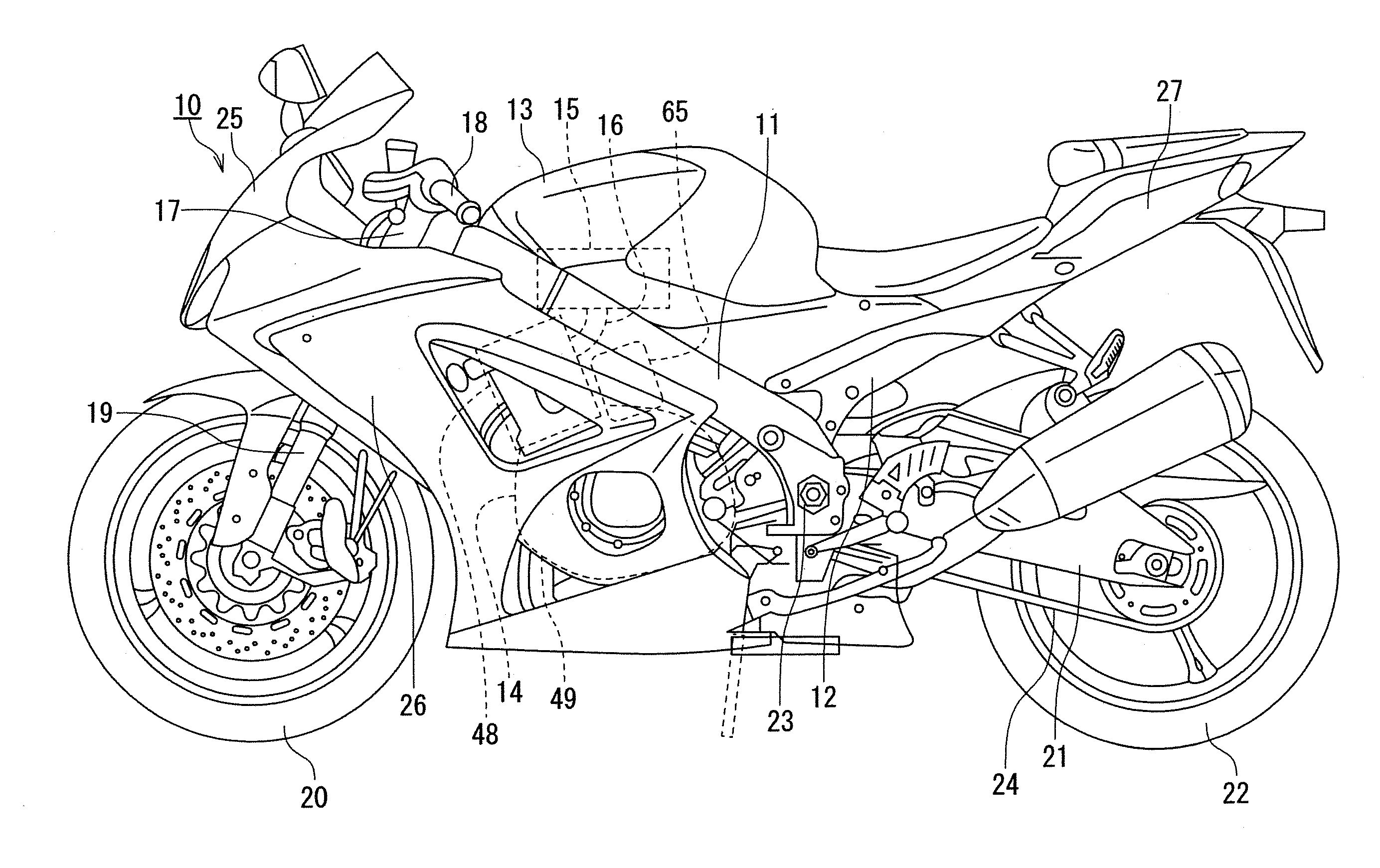
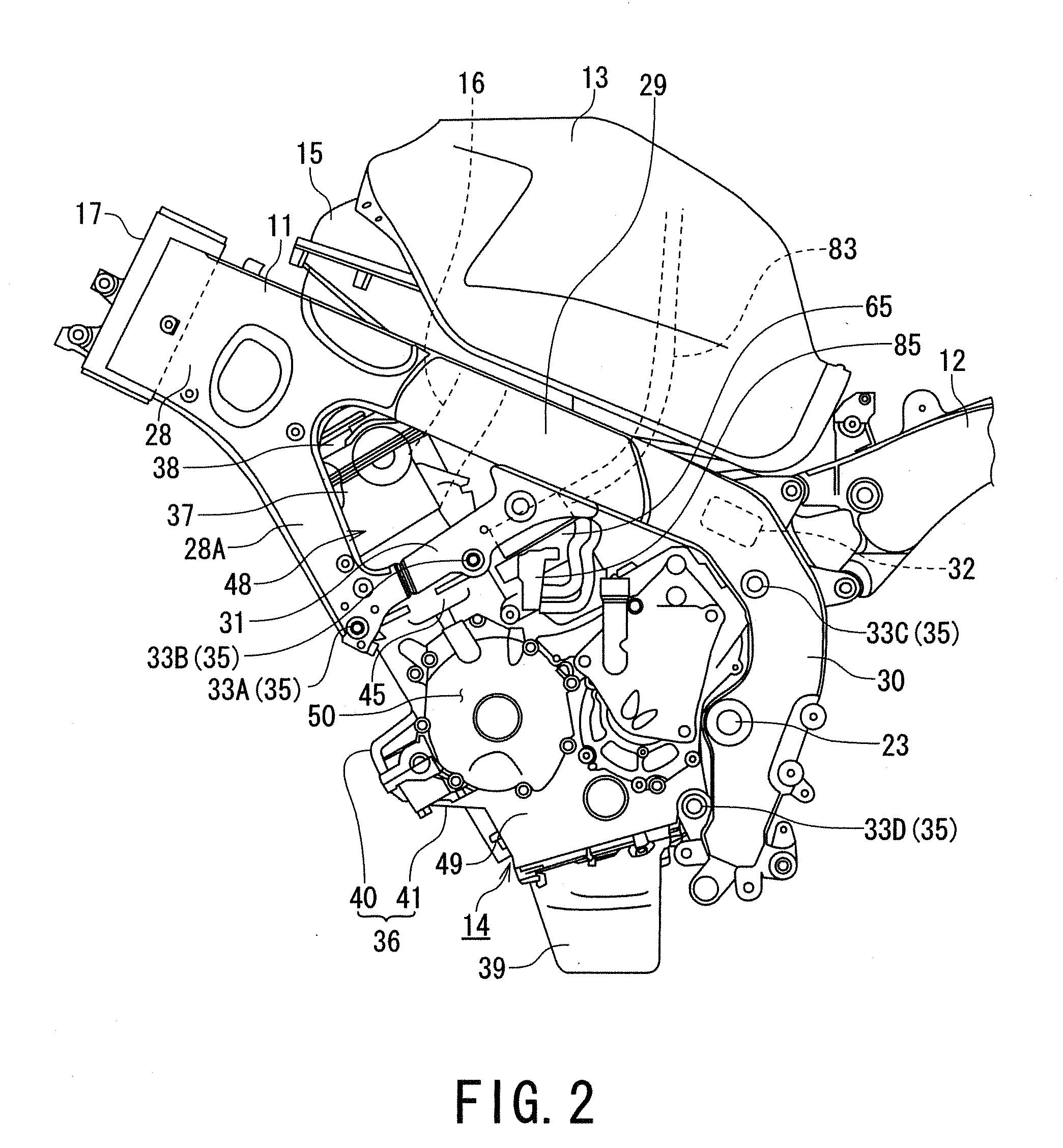
[0013]According to at least one disclosed embodiment, the canister is arranged on the rear side of the cylinder assembly of the engine and on the upper side of the crankcase of the engine. Therefore, the canister can be arranged near the center of gravity of a vehicle, thereby improving the kinetic performance of the vehicle. Moreover, the canister is arranged inside the main frame, thereby preventing a direct impact from being applied to the canister when the vehicle rolls over.
[0014]According to at least one disclosed embodiment, the canister is arranged in the engine room, and the heat from the engine is hence applied to the canister at the engine operation start period, thereby reducing a volume of the evaporated fuel gas adsorbed by the canister, and allowing an excess evaporated fuel gas to be fed into an intake pipe at an early stage of the engine start. Thus, the evaporated fuel gas adsorbed by the canister can be consumed at an early stage of start of the engine, thereby achieving a stable engine operation.
[0015]A motorcycle provided with such specific canister device can also attain an improved operational advantageous effect.

Problems solved by technology

Conventionally, it is known that in a fuel tank of a motorcycle, accumulated fuel is vaporized and retained in an upper portion of the fuel tank as an evaporated fuel gas, and leakage of the evaporated fuel gas into the air during an engine operation stop time may result in wasteful use of the fuel and adverse influence to environment.
However, in the apparatus described in Patent Document 1, since the canister is arranged on the seat rail, the canister is mounted in a position apart from the center of gravity of a vehicle, resulting in reduction of kinetic performance of the vehicle.

Method used


Image

  • Canister device for motorcycle
  • Canister device for motorcycle
  • Canister device for motorcycle

Examples


Embodiment Construction

[0028]Hereunder, a best mode for carrying out the disclosed embodiments will be described with reference to the drawings. Further, it is to be noted that the present invention is not limited to the embodiment and also noted that terms such as “upper”, “lower”, “right”, “left” and the like terms indicating positions or directions are used herein with reference to the illustrations of the drawings or an actual state of a driver riding on a vehicle.

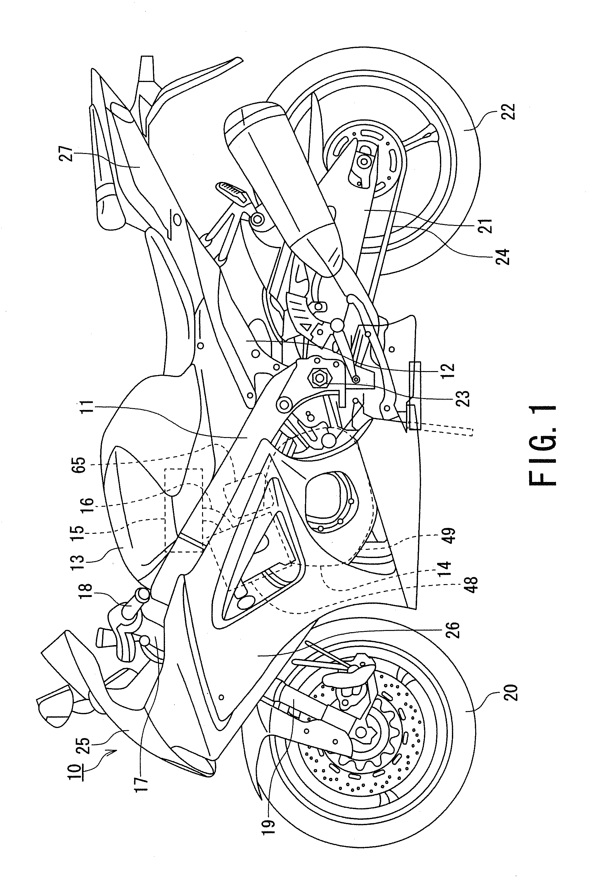
[0029]For example, with reference to FIG. 1, a motorcycle 10 is provided with a canister device according to this embodiment. The motorcycle 10 is so-called sport-type motorcycle with an entire vehicle covered with an exterior component. The motorcycle 10 includes a long main frame 11 arranged in a front / rear (longitudinal) direction substantially at an intermediate portion of the vehicle (motorcycle), and a seat rail 12 extending rearward and upward from a rear portion of the main frame 11 constitute a vehicle body frame.

[0030]The motorcycl...


PUM


Abstract

A motorcycle includes a pair of left and right main frames, a fuel tank placed on an upper side of the main frames, an engine suspended on a lower side of the main frames and provided with a cylinder assembly and a crankcase, and a canister that adsorbs an evaporated fuel gas generated in the fuel tank, wherein the canister is arranged inside the main frames in a plan view of the motorcycle and is disposed on a rear side of the cylinder assembly and on an upper side of the crankcase of the engine in a side view of the motorcycle.

Description

PRIORITY CLAIM[0001]This patent application claims priority to Japanese Patent Application No. 2010-138528, filed Jun. 17, 2010, the disclosure of which is incorporated herein by reference in its entirety.BACKGROUND[0002]1. Field of the Invention[0003]Disclosed embodiments relate to a canister device for a motorcycle which is provided with a canister which adsorbs an evaporated fuel gas in a fuel tank and feeds the evaporated fuel gas to the engine, and also relates to a motorcycle provided with such canister.[0004]2. Related Art[0005]Conventionally, it is known that in a fuel tank of a motorcycle, accumulated fuel is vaporized and retained in an upper portion of the fuel tank as an evaporated fuel gas, and leakage of the evaporated fuel gas into the air during an engine operation stop time may result in wasteful use of the fuel and adverse influence to environment.[0006]In order to solve such adverse matters, Patent Document 1 (Japanese Patent Laid-Open Publication No. 8-142959) di...

Claims


Application Information

Patent Timeline
IPC IPC(8): B62K11/02F02M33/02
CPCB60K15/03504B60K2015/03514B60Y2200/12B62J35/00F02M25/089B62K11/04F02B61/02F02M25/0854F02M25/0872B62J37/00
Inventor TANAKA, KOICHI
Owner SUZUKI MOTOR CORP
Learn More