Feed section of a separation column

a separation column and feed section technology, applied in vacuum distillation separation, separation processes, liquid degasification, etc., can solve the problem of substantial flashing of the feed stream, and achieve the effect of facilitating ideal gas mixing and reducing the maximum magnitude of local velocity

Active Publication Date: 2011-12-22
NESTE OIL OY
View PDF8 Cites 3 Cited by
  • Summary
  • Abstract
  • Description
  • Claims
  • Application Information

AI Technical Summary

Benefits of technology

[0013]It is an object to provide a feed distribution device which substantially prevents the flashing of the feed stream until it exists the feed distribution device by maintaining the pressure of the feed stream high enough. The maintaining of the pressure is achieved by arranging holes with sufficient pressure drop to the said feed distribution device in which the flashing or vaporization takes place. More specifically, the flashing of the feed stream substantially occurs when the stream flows through the holes and the flow through the holes is in choked (or critical) conditions.
[0014]Additionally, it is an object of the present invention to provide a feed distribution device which can be used to distribute the gas produced by flashing of the feed more evenly along the cross-sectional area of a separation section above the feed location compared to the distribution with no or other feed distribution devices.
[0015]An additional object of the present invention is, alone or in conjunction with distributing the feed more evenly, to use the feed distribution device to reduce the maximum magnitude of local velocity of at least a portion of the gas flashed from the feed as it is introduced to a separation section above the feed location.
[0016]A further object of the present invention is to facilitate ideal mixing of the gas produced by flashing of a feed uniformly with gas coming from a separation section below the feed inlet section.

Problems solved by technology

More specifically, the flashing of the feed stream substantially occurs when the stream flows through the holes and the flow through the holes is in choked (or critical) conditions.

Method used


Image

  • Feed section of a separation column
  • Feed section of a separation column
  • Feed section of a separation column

Examples


Embodiment Construction

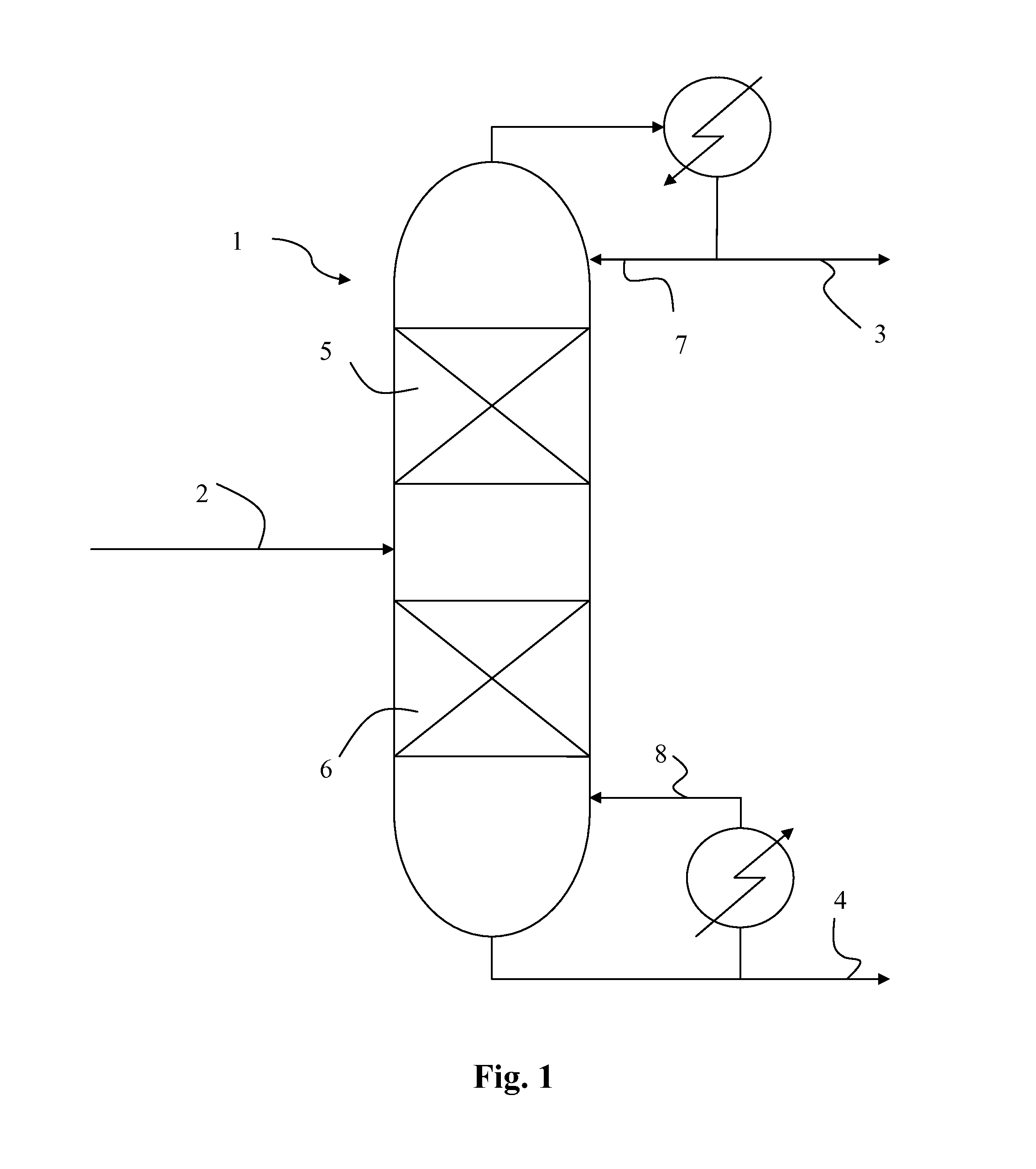
[0023]There are numerous types and variations of contacting device columns. Some of the standard contacting device columns are distillation columns, stripping columns and absorption columns. In addition to columns with a single purpose, many contacting columns are combinations of two or more standard processes (i.e. distillation and absorption). Further, there are categories such as packed columns and vacuum columns. One of ordinary skill in the art will recognize the applicability for the present invention in all of the types and variations of contacting devices enumerated above in addition to those not specifically enumerated but art recognized, where such flashing feed conditions have at least the potential to exist.

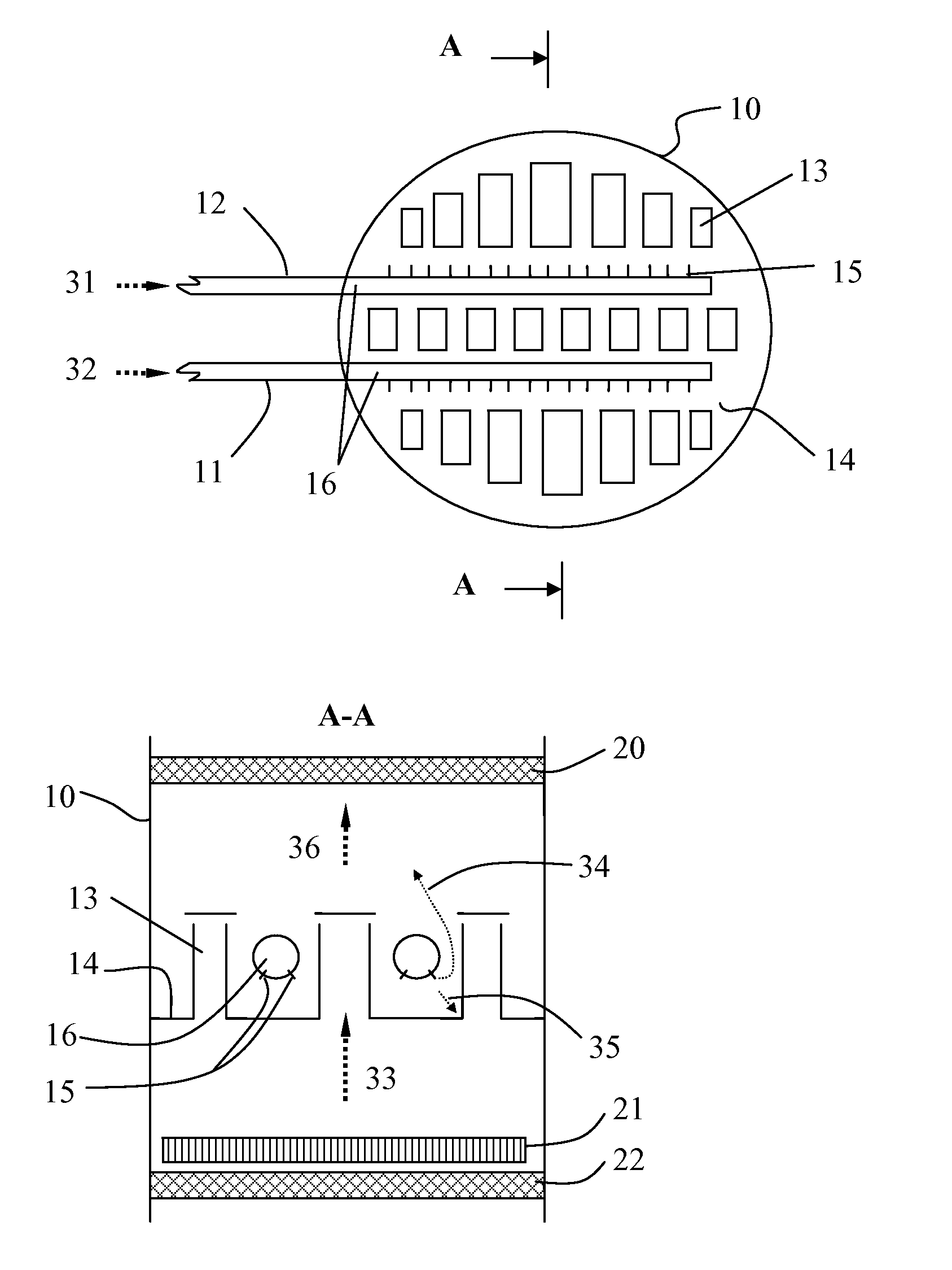
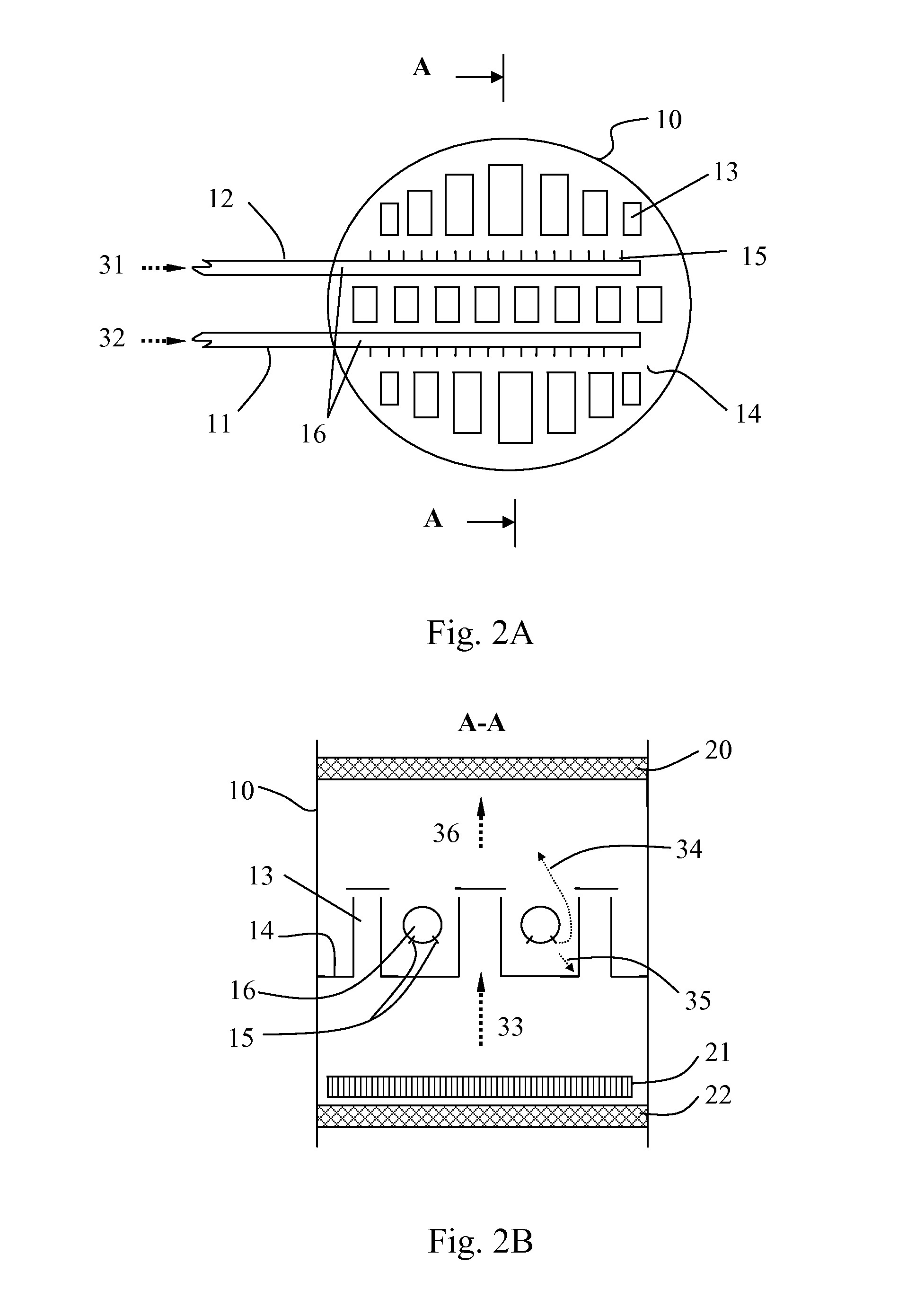
[0024]FIG. 1 shows a contacting device column 1 as a vacuum distillation column with one main feed inlet 2 and two outlets 3 and 4. One outlet is provided for each product to be separated from the feed by the separation sections, 5 provided above and 6 provided below ...


PUM

PropertyMeasurementUnit
diameteraaaaaaaaaa
diameteraaaaaaaaaa
diameteraaaaaaaaaa

Abstract

The present invention relates to a feed distribution device in separation columns and a method of operation. In particular it relates to distillation columns in which the feed stream is substantially liquid phase, or a mixture of gas and liquid upstream of the column, but where the feed vaporizes or vaporizes more when it enters the column. More specifically, the feed distribution device contains a plurality of opening which allow the feed to vaporize inside the column and where the openings are maintained in critical condition during operation. Significant advantage is achieved through the implementation and use of the present feed distribution device.

Description

FIELD OF INVENTION[0001]The present invention generally relates to separation columns. In particular it relates to distillation columns in which the feed stream is liquid phase, or a mixture of gas and liquid upstream of the column, but where the feed vaporizes or vaporizes more when it enters the column. Such columns contain a section of the column into which a feed flow is directed from one or more inlets. There is a need in the field to improve the introduction of the feed stream to such columns and to improve the feed distribution into such sections.GENERAL DESCRIPTION OF THE ART[0002]Flashing is a common phenomenon in distillation columns where at least a portion of a feed stream changes phases when reduced to the prevailing pressure inside the column. The resultant feed stream entering the column is then a gas / liquid mixture. Based on the processing requirements it has proven difficult in application to efficiently and effectively introduce such a feed to a column.[0003]When t...

Claims


Application Information

Patent Timeline
Patent Type & Authority Applications(United States)
IPC IPC(8): B01D3/10B01F3/04
CPCB01D3/008B01D3/20B01D3/32B01D19/0036B01D3/06B01D19/0063B01D3/14B01D1/06B01D19/0094
Inventor TAMMINEN, ESAHAPPONEN, MATTIHAPPONEN, ULLAJORTIKKA, SIMORUSKOAHO, MARTTI
Owner NESTE OIL OY
Why Eureka
Try Eureka