Case for Portable Electronic Device

a portable electronic device and case technology, applied in the field of cases for portable electronic devices, can solve the problems of reducing affecting the functionality of the device,

Inactive Publication Date: 2011-12-22
VINCI BRANDS LLC
View PDF10 Cites 104 Cited by
  • Summary
  • Abstract
  • Description
  • Claims
  • Application Information

AI Technical Summary

Benefits of technology

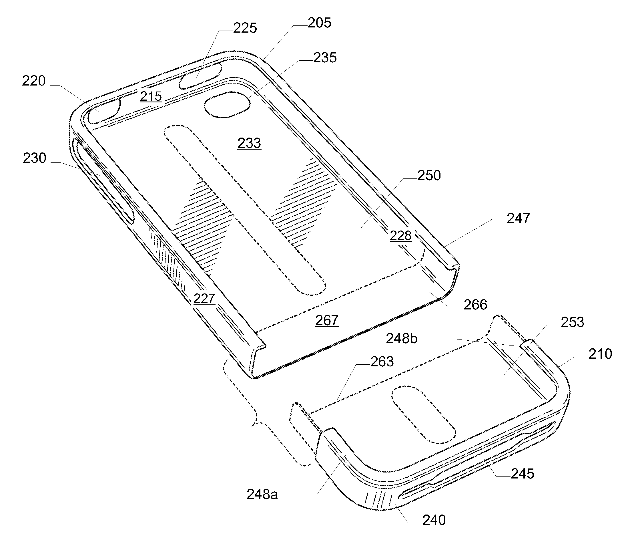
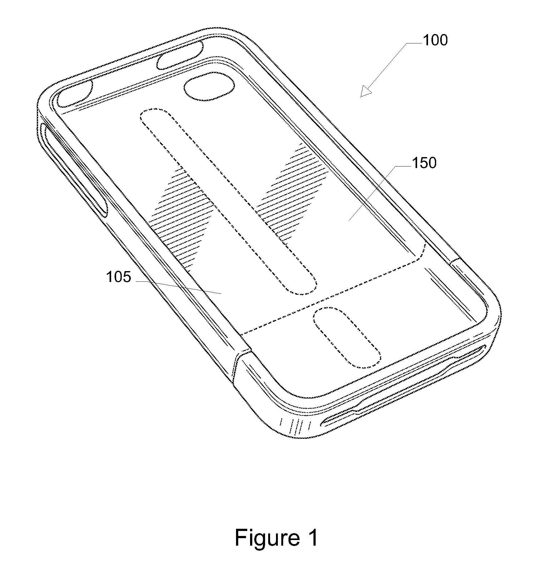
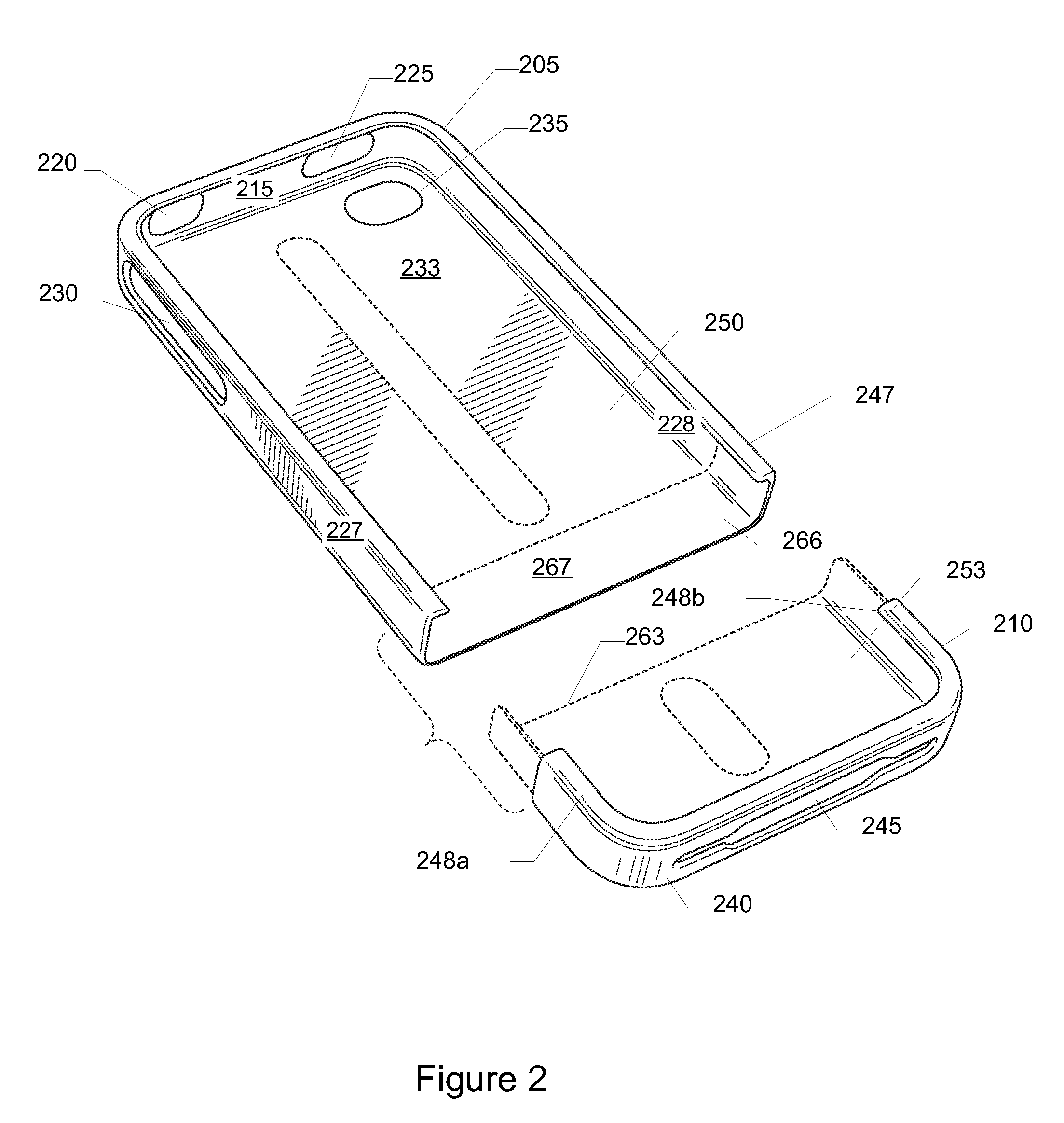
[0007]In a specific implementation, a case for a portable electronic device includes a top part and a bottom part. The top and bottom parts join together to form a horizontal part line. The top part has first and second combined access holes. The first combined access hole is on a back of the top part. The second combined access hole is on a side of the top part. The first combined access hole is for a camera lens and flash of the electronic device. The second combined access hole is for volume and ringer controls of the electronic device. The top and bottom parts further included a protective spine on an inside or interior surface of the top and bottom parts. The protective spine helps to protect the electronic device from scratches, provides shock absorption, and ensures a tight and secure fit. In a specific implementation, the protective spines include overmolded thermoplastic elastomers (TPE).
[0008]The bottom part includes a third combined access hole on a lower sidewall, an overlap, and a part line. The third combined access hole allows access to a 30-pin connector and keeps the speaker holes of the electronic device open. The overlap can keep the case together without the electronic device being encased within the case. The overlap can also create a secure connection between the two parts (top and bottom parts) when the portable electronic device is loaded. The part line aligns with a bottom edge of the display of the electronic device. The bottom part can come off (i.e., can be removed from the top part), for loading and unloading. Removal of the bottom part can allow for docking without removing the top part.

Problems solved by technology

As such, these devices are more vulnerable to damage as compared to nonportable devices.
These devices are more likely to be accidentally dropped, hit, or scratched.
However, other types of damage may ruin or limit the functionality of the device.
Often these devices contain sensitive and fragile components (e.g., screen, camera lens, flash, processors, accelerometers, and sensors).
Accidentally dropping the device could render various features unusable.

Method used


Image

  • Case for Portable Electronic Device
  • Case for Portable Electronic Device
  • Case for Portable Electronic Device

Examples


first embodiment

[0094]FIG. 6D shows the back opening. A case having this back opening may be referred to as an opaque case with a pill-shaped hole. This back opening shape may be described as an oval or a pill-shaped hole and may be similar to the back opening shown in FIGS. 6A-6B.

second embodiment

[0095]FIG. 6E shows a back opening 640 for a case. This case may be referred to as an opaque case with an egg-shaped hole. The shape of this back opening may be described as egg-shaped, pear-shaped (e.g., pyriform), or teardrop-shaped. The shape may be described as a triangle with rounded corners or a sector with rounded corners and ends. In a specific implementation, this back opening has a length of about 13 millimeters and a width of about 9 millimeters.

[0096]In this specific implementation, the shape of the back opening includes a first line 642, second line 644, first arc 646, and second arc 648. The first arc is connected to ends of the first and second lines. The second arc is connected to opposite ends of the first and second lines. The first arc is different from the second arc. For example, a size of the first arc may be greater than the second arc, the first arc may have a greater degree of curvature than the second arc, the first arc may have a greater radius than the se...

third embodiment

[0103]FIG. 6F shows a back opening 650 for a case. The shape of this back opening may be described as keyhole-shaped. This case may be referred to as an opaque case with combined holes. In a specific implementation, this back opening has a length of about 13 millimeters and a width of about 9 millimeters.

[0104]The shape of this back opening includes straight lines and curves. In this specific implementation, the shape of the back opening includes a first line 652, second line 654, first arc 656, and second arc 658. The first arc is connected to ends of the first and second lines. The second arc is connected to opposite ends of the first and second lines. The first arc is different from the second arc.

[0105]In this specific implementation, a length of the first arc is greater than a length of the second arc. The first arc, second arc, or both may be portions of a circle, oval, or ellipse. An arc or a portion of an arc may have constant radius, an increasing radius, or a decreasing ra...


PUM


Abstract

A case for an electronic device protects the electronic device. The case has a lower case portion and an upper case portion, which assemble together to protect the electronic device. A back of the case can include a back opening to expose a camera lens and flash of the electronic device or first and second back openings. The first back opening exposes the camera lens. The second back opening exposes the flash.

Description

CROSS-REFERENCE TO RELATED APPLICATIONS[0001]This patent application claims the benefit of U.S. provisional applications 61 / 355,441, filed Jun. 16, 2010, and 61 / 365,302, filed Jul. 16, 2010; 61 / 367,296, filed Jul. 23, 2010, and is a continuation-in-part of U.S. patent application Ser. Nos. 29 / 363,974, filed Jun. 16, 2010; 29 / 364,348, filed Jun. 22, 2010; and 29 / 364,447, filed Jun. 23, 2010. These applications are incorporated by reference along with all other references cited in this application.BACKGROUND OF THE INVENTION[0002]This invention relates to a case for portable electronic devices. There are many types of portable electronic devices including personal digital assistants (PDAs), computers, smartphones, mobile phones, satellite phones, cellular phones, pagers, music player, MP3 players, media players, digital cameras, video cameras, bar code scanner, global positioning system (GPS), and portable game consoles.[0003]These portable electronic devices allow people to play and ...

Claims


Application Information

Patent Timeline
Patent Type & Authority Applications(United States)
IPC IPC(8): H05K5/02
CPCH04B1/3888H05K5/02H05K5/0086B33Y80/00B26F1/38
Inventor DIEBEL, MARKUS
Owner VINCI BRANDS LLC
Why Eureka
Try Eureka