System and method for microwave ranging to a target in presence of clutter and multi-path effects

a microwave range and clutter technology, applied in the field of electromagnetic distance measurement, can solve the problems of limited bandwidth of transmitted pulses, difficult isolation of individual targets, multipath effects,

Active Publication Date: 2011-12-22
AMTECH SYST
View PDF2 Cites 26 Cited by
  • Summary
  • Abstract
  • Description
  • Claims
  • Application Information

AI Technical Summary

Benefits of technology

[0008]An example of the geometry of a conventional radar system is shown in FIG. 1. The radar system transmits a RF signal which is reflected from the objects in the field of the radar and are received by the radar system. Strong multipath signals may occur from a radio path bounced from the radar system to a flat surface (ground for example), to targets, and return. A sample plot of signals is shown in FIG. 2. To measure the distance to a single desired target, the correct return signal of the many in FIG. 2 is required.

Problems solved by technology

However, an individual target may be difficult to isolate if there are many reflectors in the field of the radar system.
Also, the distance calculation may be corrupted by multipath effects and limited bandwidth of the transmitted pulse.
However, this technique is fraught with problems if the reflected signal from the desired target is hidden by signals reflected from other objects in the field of the radar system.
Backscatter RFID readers transmit CW signals while acquiring data from tags, and thus lack the capability of ranging using measurement of time-of-flight methods.
These modulation waveforms lack nanosecond precision needed to use time-of-flight methods to measure distance to a resolution on the order of a meter or less between tags and readers.
RFID systems using time-of-flight methods to determine object location may be found in the art but these types of systems are expensive, require careful installation, use expensive tags and require precise positioning of the system components.
Signal strength methods to determine tag location may also be found in the art, but these types of systems lack accuracy and precision.
These timings cannot be used for time-of-flight calculations since there is no absolute time reference to establish a time base for calculation.
Another practical problem is that the transitions from one modulation state to the other lack the bandwidth, precision and definition in timing required for nanosecond resolution required for ranging.

Method used


Image

  • System and method for microwave ranging to a target in presence of clutter and multi-path effects
  • System and method for microwave ranging to a target in presence of clutter and multi-path effects
  • System and method for microwave ranging to a target in presence of clutter and multi-path effects

Examples


example 1

[0075]The following simulation illustrates the process of ranging to a tag using the process outlined above.

[0076]The radar ranging process used in this example performs a subtraction of processed signals:[0077]Transmit radar signals coordinated with the modulation state of the tag[0078]Receive reflected radar signals for each of the modulation states of the tag[0079]Use an analog to digital converter (A / D) or equivalent to sample the signals[0080]Process each of the sampled signals using a fast Fourier transform (FFT) to produce complex signal spectrums[0081]Form the complex conjugate of the FFT of the transmit signal[0082]Form products by multiplying the complex conjugate of the transmit signal with the FFT of each received signal individually[0083]Produce a correlation for each received signal individually by performing an inverse FFT of each product[0084]Subtract the correlation obtained with the tag modulation in one state from the correlation with the tag modulation in the oth...

example 2

[0091]A second example follows the process of Example 1 with several modifications. In this example, parameters and modulations are chosen to improve performance.

[0092]Example 2 uses the following parameters:[0093]A transmit chirp radar signal with constant amplitude (other than limited rise and fall times) with a frequency that increases linearly by 100 MHz in 2048 ns[0094]Rise and fall times limited to 100 ns to reduce out of band emissions[0095]Downconvert the received signals into the band from 50 MHz to 150 MHz[0096]Clutter consisting of two stationary targets, the return radar signal from the first has a round trip time delay of 60 ns and a relative strength of 1, and the return radar signal from the second has a round trip time delay of 70 ns and a relative strength of 0.3[0097]A radar return signal from a tag with a round trip time delay of 65 ns and a relative strength of 0.2 when modulating in Mode B and 0.0 when modulating in Mode A[0098]Uncorrelated white Gaussian noise ...

example 3

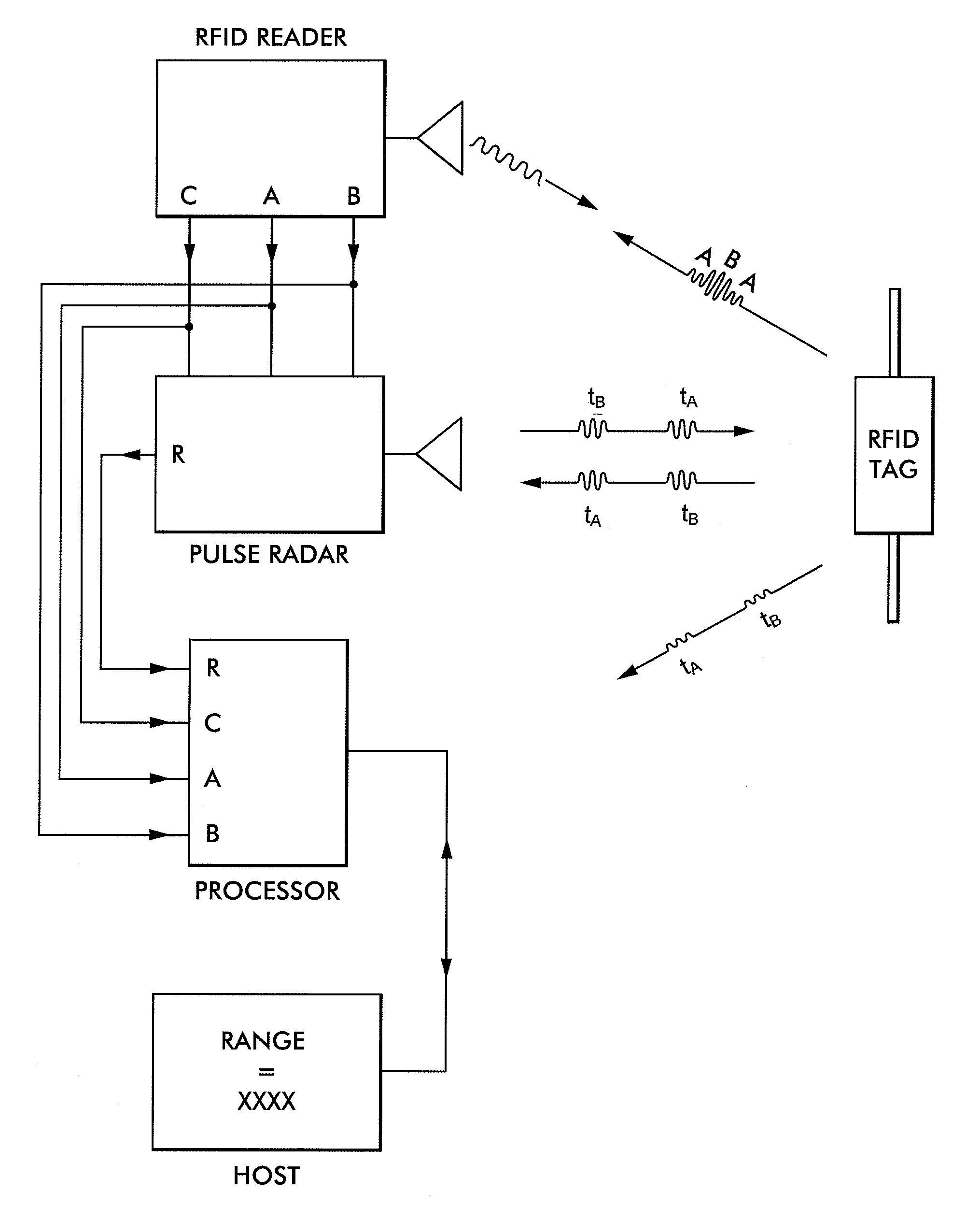
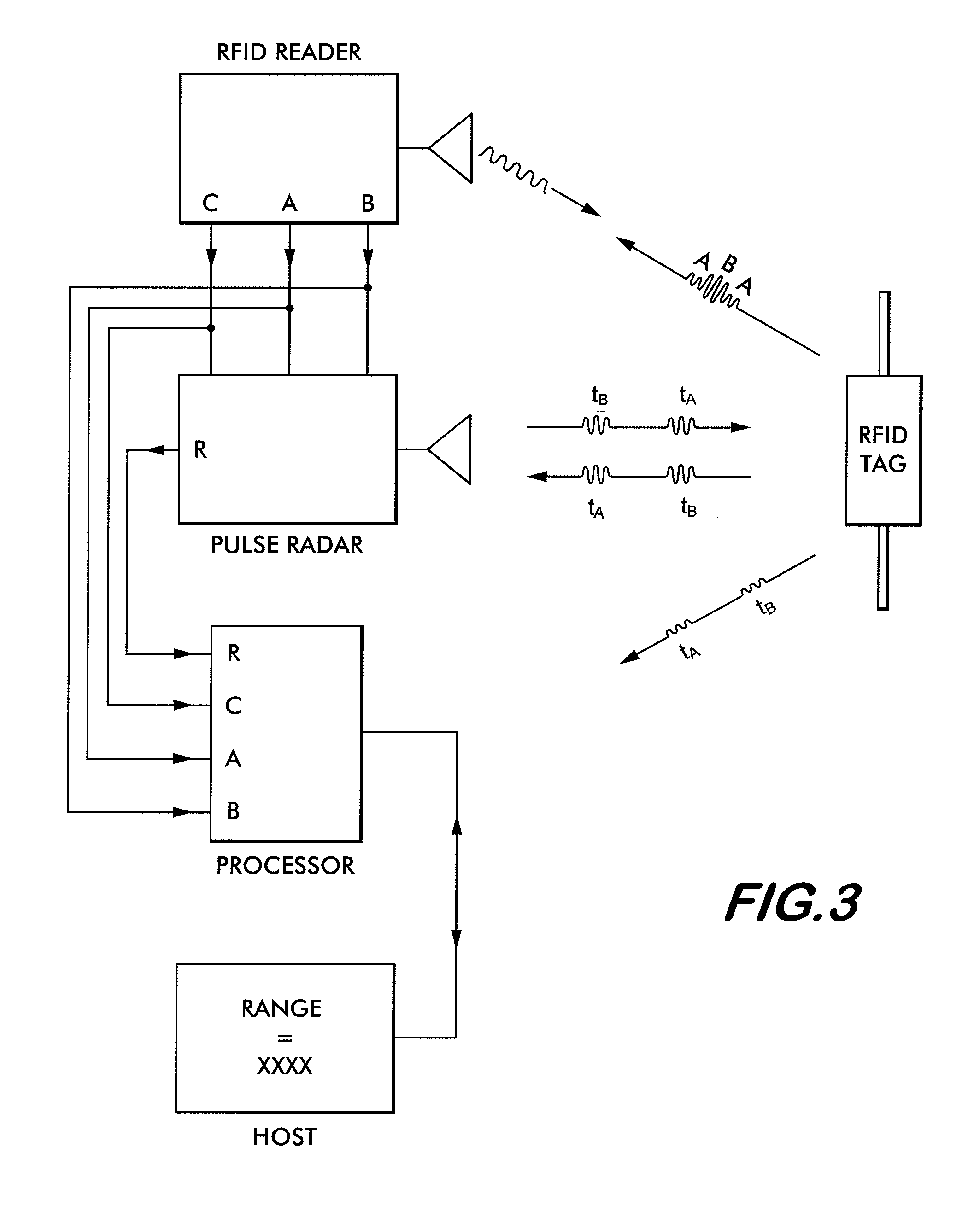
[0104]Methods shown in Example 1 and Example 2 illustrate the technique of differential pulse compression radar to measure the distance to a tag in the presence of clutter and multipath. Example 2 also shows the ability of the methods to suppress amplitude noise as shown in FIG. 6b through FIG. 6g. Implementation of the methods are improved by consistency in timing, frequency and amplitude and minimizing jitter of the transmitted radar pulses and subsequent data processing. An improved differential pulse compression radar is shown in FIG. 7. The RFID Reader, Host and data processing sections of FIG. 3 have been omitted for clarity.

[0105]Operation is performed using a minimum set of signals. First, timing is derived from a signal (from a reader or other source) indicting the modulation state of the tag being read. An example of such a signal is the “TAG MODULATION STATE” of FIG. 4 and “Modulation State from Reader” on FIG. 7. Further referring to FIG. 7, Signal Generator 1 (Agilent M...


PUM


Abstract

A system for measuring the range to an RFID tag including situations containing high clutter and multi-path signals is disclosed. The system includes an RFID reader; an RFID tag; and a coordinated pulse compression radar system. In the system the RFID reader causes the tag to respond to received signals in a first backscatter state at a first time and a second backscatter state at a second time. The pulse compression radar system transmits short pulses coordinated by the backscatter state of the RFID tag and the system creates a differential signal comprised of the differences between radar signals obtained during the first and second states of the tag to obtain an uncorrupted measure of a round trip time of flight of said radar pulses between the pulse radar system and the RFID tag.

Description

CROSS-REFERENCE TO RELATED APPLICATIONS[0001]This utility application claims the benefit under 35 U.S.C. §119(e) of Provisional Application Ser. No. 61 / 355,824, filed on Jun. 17, 2010, entitled System and Method for Microwave Ranging to a Target in Presence of Clutter and Multi-path Effects, and also claims benefit under 35 U.S.C. §120 as a continuation-in-part of Utility application Ser. No. 13 / 095,296 filed on Apr. 27, 2011, also entitled System and Method for Microwave Ranging to a Target in Presence of Clutter and Multi-path Effects. The entire disclosures of these applications are incorporated by reference herein.FIELD OF INVENTION[0002]This invention relates to the field of electromagnetic distance measurement and, in particular, distance measurement to an RFID device.BACKGROUND OF THE INVENTION[0003]A radar system may measure the distance to a target through measurement of the round-trip time-of-flight of the radar signal to a target and return. The one-way distance, d, to a ...

Claims


Application Information

Patent Timeline
Patent Type & Authority Applications(United States)
IPC IPC(8): G01S13/32
CPCG01S13/751G01S7/023G01S13/765G01S7/2813G01S7/285G01S13/20G01S13/28G06K7/10297
Inventor GRAVELLE, KELLYLANDT, JEREMYLUNSFORD, PATRICK W.
Owner AMTECH SYST
Why Eureka
Try Eureka