Adaptive sidelobe blanking for motion compensation

a technology of motion compensation and sidelobe, which is applied in the direction of direction finders using radio waves, instruments, and reradiation, etc., can solve the problems of difficult mechanical approach, limited ability to rotate such antenna patterns, and small number of antenna elements for auxiliary antennas

Active Publication Date: 2011-12-22
RAYTHEON CO
View PDF0 Cites 22 Cited by
  • Summary
  • Abstract
  • Description
  • Claims
  • Application Information

AI Technical Summary

Benefits of technology

[0016]In accordance with the teachings of the present invention, during antenna system operation, the ship motion compensator component in response to platform motion signals indicative of changes in platform pitch, yaw and roll angles generates a new set of weighting coefficient values from the initial set of weighting coefficient values provided by the memory as a function of such pitch, yaw and roll angles change. The changes in both amplitude and phase weighting coefficient values result in both the quadrant phase rotation and the element weighting rotation. Such rotations compensate for changes in roll angle by spreading out the auxiliary antenna pattern received from the auxiliary antenna making sidelobe coverage broad enough to cover a tilted horizon frame of reference in terms of elevation angle and an extended region in azimuth. The compensation for pitch and yaw angles is achieved by simply changing the quadrant phase values either before or following roll compensation changes. This causes the received auxiliary beam to be electronically steered toward the horizon.

Problems solved by technology

One reason is that the use of a mechanical approach is difficult due to the mounting axle being inline with the radar beam.
The alternative approach is electronic beam steering however; the number of antenna elements for the auxiliary antenna is usually very small.
Hence, the capability of rotating such antenna pattern is very limited.

Method used


Image

  • Adaptive sidelobe blanking for motion compensation
  • Adaptive sidelobe blanking for motion compensation
  • Adaptive sidelobe blanking for motion compensation

Examples


Embodiment Construction

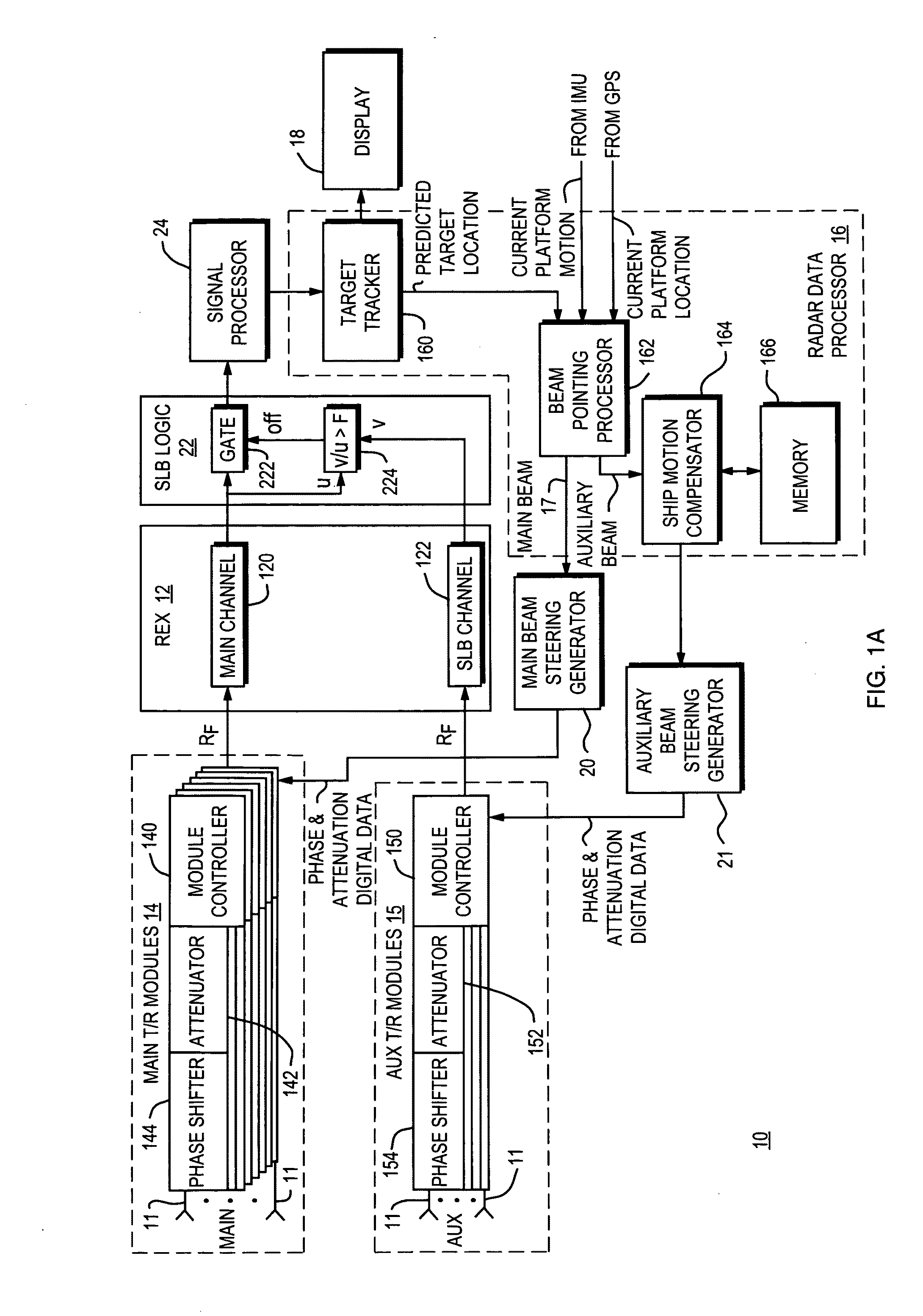
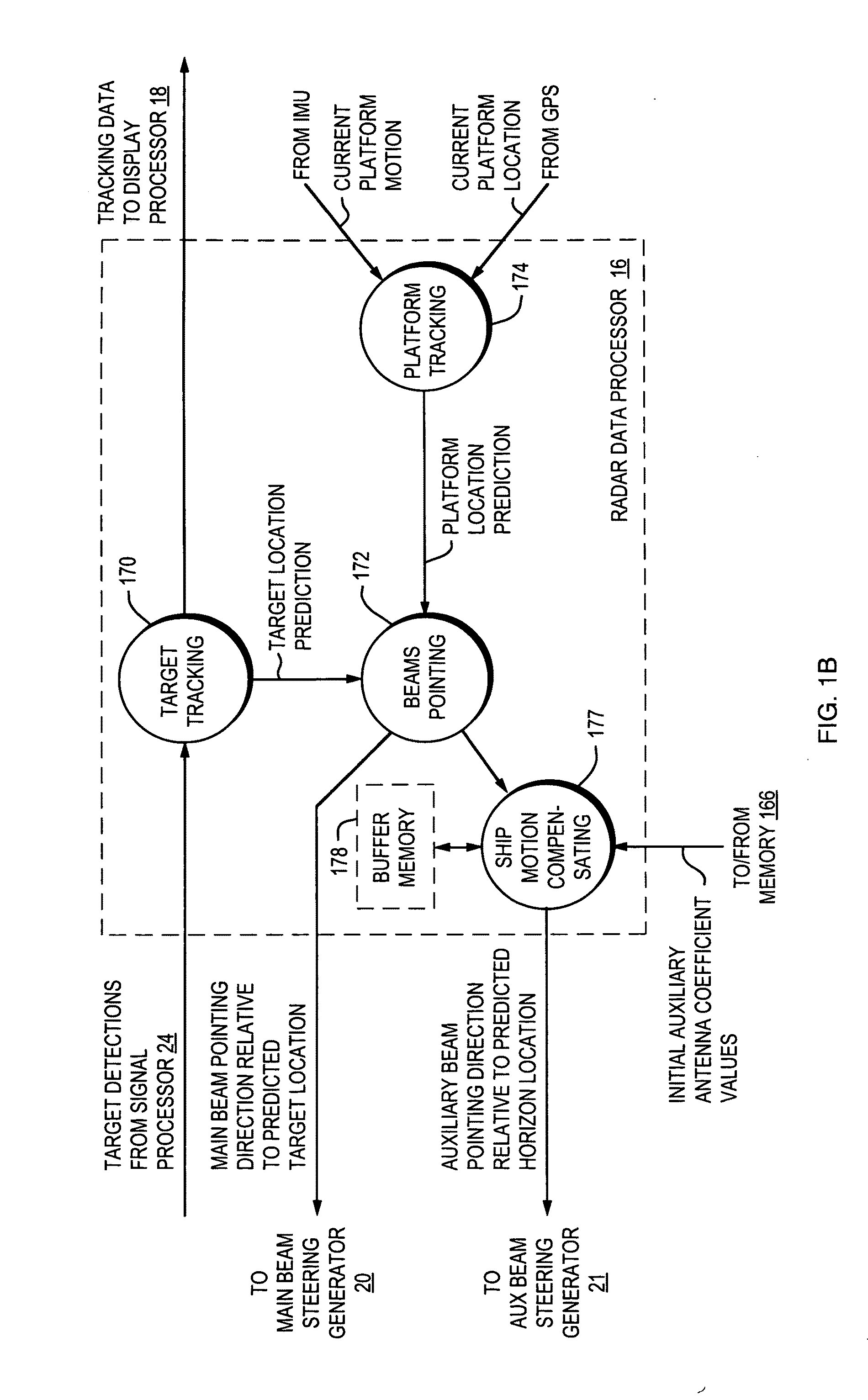
[0029]Referring to FIG. 1A, there is shown an illustrative embodiment of the present invention which comprises a moving platform phased array radar system 10 incorporating the motion compensation method and system of the present invention. In the illustrated embodiment, the motion compensation system is utilized for carrying out effective sidelobe blanking for a shipboard moving platform based antenna system. Obviously, the motion compensation system may also be used for other types of moving platform antenna systems without departing from the teachings of the present invention. As shown in FIG. 1A, system 10 includes a plurality of conventional components that can be found in a phased array radar system. These components include a receiver / exciter (REX) component 12 that includes main and SLB auxiliary antenna channels 120 and 122 respectively which couple to a plurality of main and auxiliary transmit / receive (T / R) modules 14 and 15 respectively, a radar data processor 16 coupled t...


PUM


Abstract

A motion compensation method and system is included in a radar antenna system mounted on a moving platform which is subject to pitch, yaw and roll. The radar antenna system includes a main array antenna, and an auxiliary antenna. The auxiliary channel associated with the auxiliary antenna utilizes roll, pitch and yaw angle motion compensations as its auxiliary antenna always steers a horizontal fan shape beam at the horizon to blank any surface (land or sea) based EM interferences. Such motion compensations are provided by a ship motion compensator component and process included within the antenna system. The ship motion compensator component in response to platform motion signals indicative of changes in platform motion angles generates new sets of values using an initial set of weighting coefficient values as a function of such angle motion changes. This produces changes in both amplitude and phase weighting coefficient values which results in both the quadrant phase rotation and the element weighting rotation. The process steers and spreads out the received auxiliary antenna pattern making sidelobe coverage broad enough to compensate for such changes in platform motion.

Description

[0001]The United States Government has rights to this invention pursuant to Contract No. N00024-04-C-5340 awarded by Department of the Defense.BACKGROUND OF THE INVENTION[0002]1. Field of the Invention[0003]This invention relates generally to antenna system design and more particularly to sidelobe blanking for use in radar motion compensation systems.[0004]2. Description of Related Art[0005]A Sidelobe Blanking (SLB) system is commonly used for mitigating interference in radar and telecommunications systems. As known in the art, the SLB system operates to compare the signal outputs of one or more low directivity auxiliary antennas to the output signal of the main antenna of the radar antenna system. When the signal level received in an auxiliary channel of an auxiliary antenna is equal to or greater than signal level in the main channel of the main antenna, the SLB system discards the main channel response as interference.[0006]In certain applications, the SLB system is designed to p...

Claims


Application Information

Patent Timeline
Patent Type & Authority Applications(United States)
IPC IPC(8): G01S13/52
CPCG01S7/023G01S7/03G01S7/36G01S7/4004H01Q3/26H01Q1/185H01Q1/32H01Q1/34H01Q3/08G01S2013/0254G01S7/0236
Inventor LOK, YUCHOI F.CHANG, KAICHIANGPOZGAY, JEROME H.
Owner RAYTHEON CO
Why Eureka
Try Eureka