
Method for data communication and device for ethernet

Inactive Publication Date: 2011-12-22
NEW H3C TECH CO LTD
View PDF18 Cites 9 Cited by
  • Summary
  • Abstract
  • Description
  • Claims
  • Application Information

AI Technical Summary

Benefits of technology

[0012]The present invention provides a method for data communication that enables a single MAC chip in an Ethernet device to support a greater number of ports, whereby the competitiveness of the Ethernet device in broadband access application is enhanced.
[0013]The present invention further provides an Ethernet device, wherein a single MAC chip in the Ethernet device can support a greater number of ports, whereby the competitiveness of the Ethernet device in broadband access application is enhanced.
[0018]From the aforementioned technical solutions it can be seen that the MAC chip in the present invention communicates with a plurality of PHY chips through a bus, wherein the technical solution of using the different addresses on the address bus to distinguish the different PHY ports on different PHY chips enable the MAC chip to support a greater number of ports and to be connected to more PHY chips in the case of having a given number of pins (i.e. equal to the number of signal lines in the bus), such that the number of users that an Ethernet device can access is increased and thus the competitiveness of the Ethernet device in broadband access application is enhanced.

Problems solved by technology

However, as compared with an XDSL device, an Ethernet device has an obvious disadvantage: the number of ports supported is relatively small.
A MII interface is consisted of 14 signal lines, which means its support is rather flexible, but a disadvantage is that too many signal lines are used for one MII interface.
The defect of the method is that a MAC layer chip cannot support a great number of ports.
Since the number of ports supported by a MAC layer chip is relatively great (e.g. 24) in the existing technology, while the number of ports supported by a PHY chip is relatively small (e.g. 8), and each port needs an independent data interface, the number of pins that a MAC layer chip needs to support is rather great, and it is difficult to support a large number such as 64 or 72.
The required number of pins being too great is a major reason why a MAC chip of an Ethernet switch cannot achieve using a signal chip to support a great number of ports at an optimal performance price ratio.

Method used


Image

  • Method for data communication and device for ethernet
  • Method for data communication and device for ethernet
  • Method for data communication and device for ethernet

Examples


Embodiment Construction

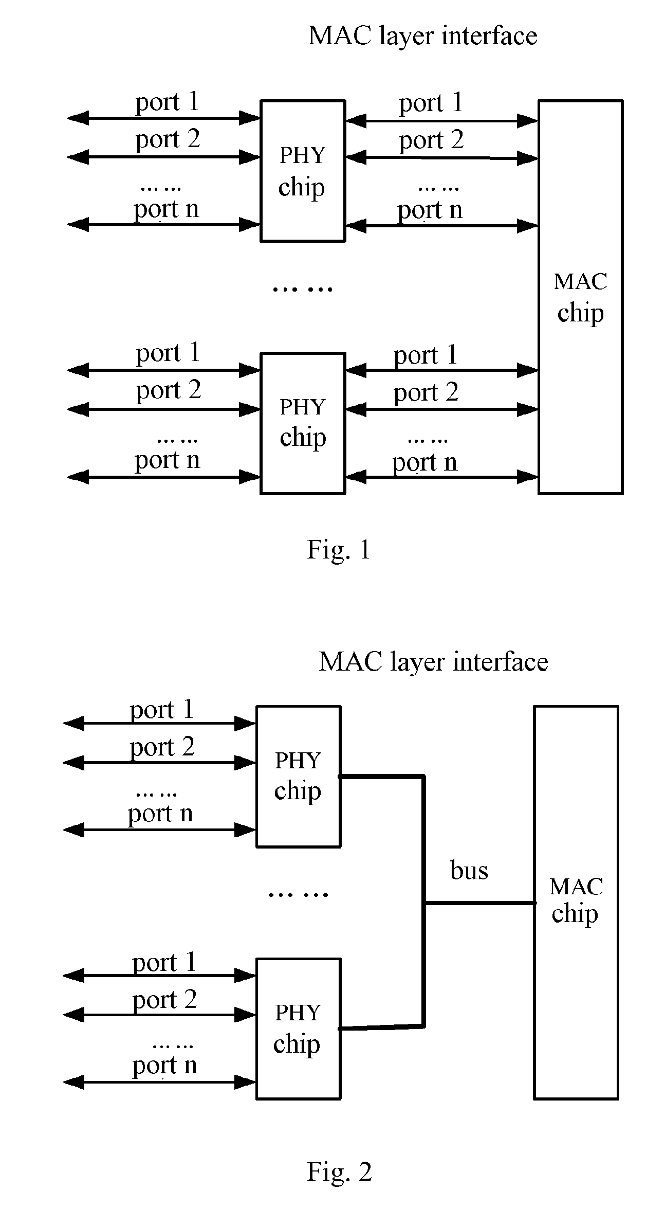
[0022]The general concept of the present invention is to change the current one-to-one interface design between a PHY chip and a MAC chip in an Ethernet device into a multi-address bus interface design and to attach bus interfaces of more than one PHY chips to a bus interface of a MAC chip through a multi-address bus uniformly so as to realize communication between the MAC chip and the more than one PHY chips, whereby a single MAC chip of the Ethernet device (such as an Ethernet switch) can support a greater number of ports.

[0023]The present invention is further explained in detail in order to make the purpose, technical solution and advantages of the present invention clearer.

[0024]FIG. 2 is an illustration of communication between a PHY chip and a MAC chip in an Ethernet device in an embodiment of the present invention. Now refer to FIG. 2, the technical solution of the present invention comprises the following key techniques:

[0025](1) A Multi-address Bus Interface is used Between...


PUM


Abstract

A method for data communication and a device for Ethernet MAC chip communicates with a plurality of PHY chips by a multi-address bus, wherein, the different ports of PHY for different PHY chips is distinguished by using the different addresses on the address bus of the multi-address bus. It causes that the MAC chip can support more number of ports, and connect to more PHY chips, so that the number of users that can access a Ethernet device is increased.

Description

TECHNICAL FIELD[0001]The present application relates to Ethernet technology and in particular to a method for data communication and a device for Ethernet.BACKGROUND ART[0002]Currently, broadband access to home technique mainly includes XDSL technique, Ethernet technique and FTTH technique, which use transmission media of telephone line, network cable and optical fiber to door respectively. After emergence of the new long-distance Ethernet technique, Ethernet technique can also use telephone line to access to home, which greatly reduces obstacle in the practical application of Ethernet. However, as compared with an XDSL device, an Ethernet device has an obvious disadvantage: the number of ports supported is relatively small. Currently, an Ethernet device (or a single board of a rack equipment) usually supports 24 ports, or at most 48 ports, while an XDSL device can support 72 ports.[0003]In practical application, there are many high-rise buildings, for example, there are about 128 h...

Claims


Application Information

Patent Timeline
IPC IPC(8): H04L12/56
CPCG06F13/00H04L69/324H04L69/32H04L69/14H04L69/321
Inventor YU, YANG
Owner NEW H3C TECH CO LTD
Features
  • Generate Ideas
  • Intellectual Property
  • Life Sciences
  • Materials
  • Tech Scout
  • Unparalleled Data Quality
  • Higher Quality Content
  • 60% Fewer Hallucinations
Learn More