Method of evaluating the horizontal speed of a drone, in particular a drone capable of performing hovering flight under autopilot

a drone and autopilot technology, applied in the field of piloting drones, can solve the problems of inability to give a satisfactory estimate of the speed of the drone, and the accuracy of the technique is not high enough

Active Publication Date: 2011-12-22
PARROT
View PDF5 Cites 94 Cited by
  • Summary
  • Abstract
  • Description
  • Claims
  • Application Information

AI Technical Summary

Benefits of technology

[0027]Another object of the invention is to be able to benefit from these advantages, even with scenes in which contrast may be very low and noise high, or even with scenes in which shapes that are identified in the image are capable of changing in appearance in unpredictable manner, as happens when a drone is overflying terrain that is very changeable and unpredictable.

Problems solved by technology

In order to establish hovering flight, there remains a problem of eliminating the linear speed of the drone.
Unfortunately, the low cost accelerometers that are used are generally too noisy to give a satisfactory estimate of the speed of the drone once the signal from them has been integrated twice.
Nevertheless, that technique suffers from lack of accuracy, particularly at the slowest speeds (when the drone is moving forwards at low speed, the scene captured presents very little change from one image to the next).
It is also extremely dependent on the presence or absence of characteristic points of interest in the scene captured by the camera: when the image is uniform, e.g. showing a wall or the sky, when outside, the quasi-absence of characteristic points make that technique ineffective.
Nevertheless, identifying the movement of the various points in the image picked up by said camera remains a task that is difficult and that depends strongly simultaneously on i) the nature of the scene (more or less contrast, changing to a greater or lesser extent); ii) the speed; and iii) the constraints of limiting the complexity of the calculations.
In contrast, that method is sensitive to rotation and changes of attitude and it does not make it possible to verify intrinsically the quality of the results given, i.e. the algorithm always delivers a result providing enough points present a large gradient, but said result is delivered even if it is meaningless.
To summarize, the optical flow method is an “all terrain” method capable of operating over a very wide range of speeds, but it delivers the result that is not always reliable, nor very accurate, in particular at low speed.
In contrast, that method imposes much greater constraints on the scene in terms of contrast and texture, which means that it is not applicable to all the situations that might be encountered.
This constraint limits the possibility of implementing conventional algorithms that are often designed to be executed on computers having processors that are fast and memory capacities that are large.

Method used


Image

  • Method of evaluating the horizontal speed of a drone, in particular a drone capable of performing hovering flight under autopilot
  • Method of evaluating the horizontal speed of a drone, in particular a drone capable of performing hovering flight under autopilot
  • Method of evaluating the horizontal speed of a drone, in particular a drone capable of performing hovering flight under autopilot

Examples


Embodiment Construction

[0045]There follows a description of an implementation of the invention.

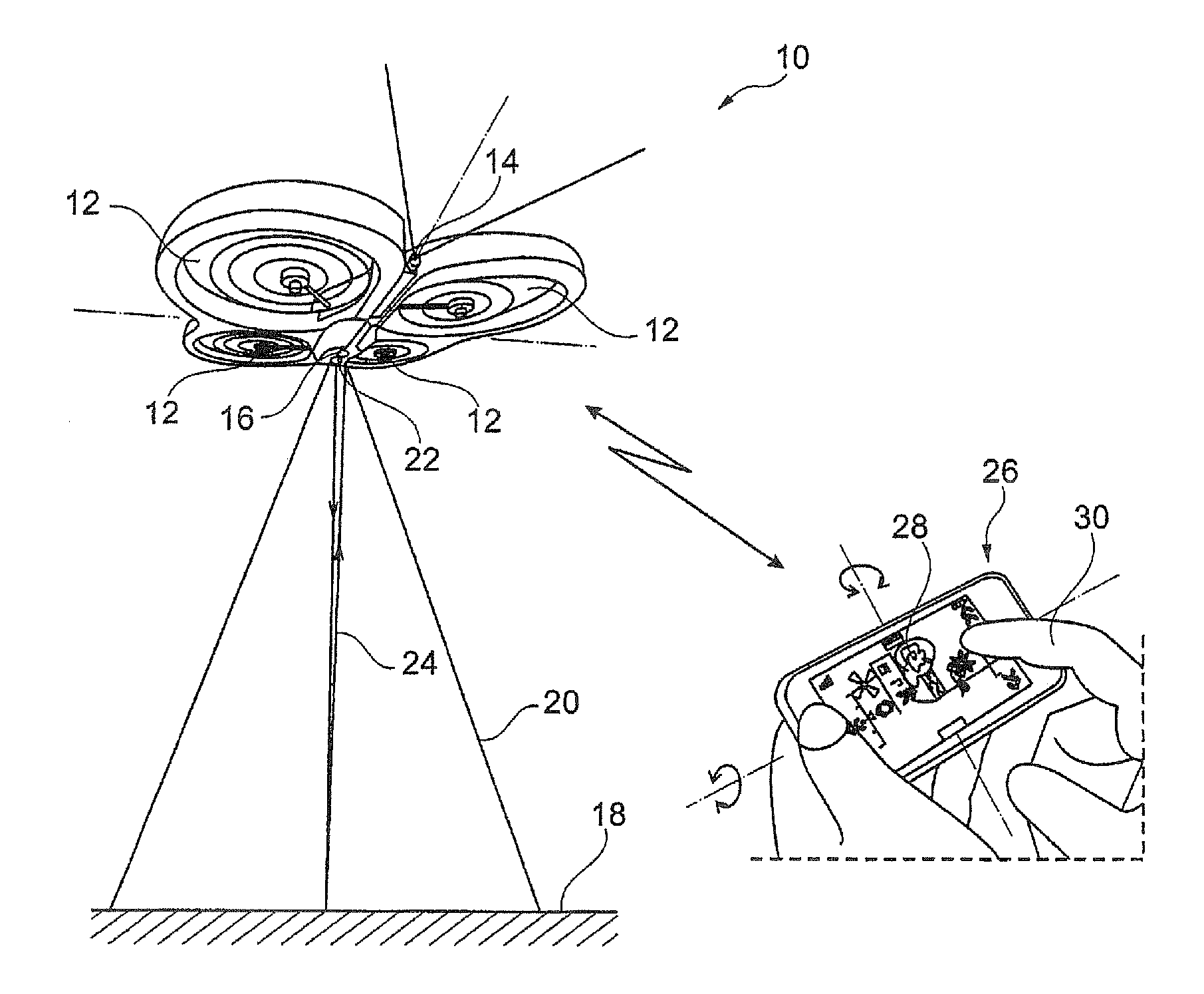
[0046]In FIG. 1, reference 10 is an overall reference to a drone, e.g. a quadricopter such as the AR.Drone model from Parrot S A, Paris, France. The drone 10 has four coplanar rotors 12 having their motors controlled independently by an integrated flying and attitude-control system.

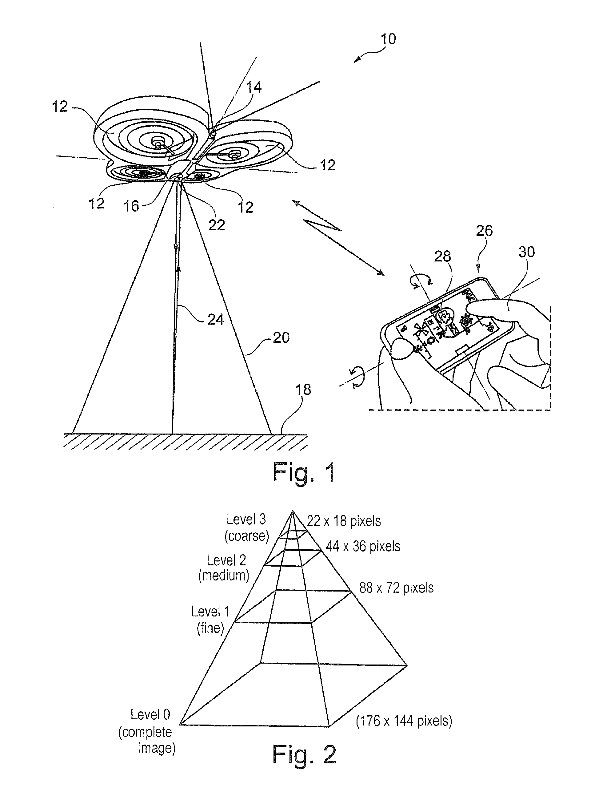
[0047]The drone 10 also includes a forward-looking first camera 14 serving to obtain an image of the scene towards which the drone is headed, and a downwardly-looking vertically-oriented camera 16 suitable for picking up successive digital images of the terrain 18 over which the drone is flying. The viewing angle of this camera, shown diagrammatically at 20, may for example have a diagonal of 64° with a resolution of 176×144 pixels (these values naturally being given purely by way of illustration).

[0048]The drone 10 is also provided with an ultrasound altimeter 22 that emits a beam 24 towards the ground serving to determine at all tim...


PUM


Abstract

The method operates by estimating the differential movement of the scene picked up by a vertically-oriented camera. Estimation includes periodically and continuously updating a multiresolution representation of the pyramid of images type modeling a given picked-up image of the scene at different, successively-decreasing resolutions. For each new picked-up image, an iterative algorithm of the optical flow type is applied to said representation. The method also provides responding to the data produced by the optical-flow algorithm to obtain at least one texturing parameter representative of the level of microcontrasts in the picked-up scene and obtaining an approximation of the speed, to which parameters a battery of predetermined criteria are subsequently applied. If the battery of criteria is satisfied, then the system switches from the optical-flow algorithm to an algorithm of the corner detector type.

Description

FIELD OF THE INVENTION[0001]The invention relates to piloting drones, in particular rotary wing drones such as helicopters, quadricopters, or the like.BACKGROUND OF THE INVENTION[0002]A typical example of such a drone is the AR.Drone from Parrot S A, Paris, France, which is a quadricopter fitted with a series of sensors (three-axis accelerometers and gyros, altimeter). The drone is also provided with a front camera capturing an image of the scene towards which the drone is headed, and a vertically-oriented camera capturing an image of the terrain over which the drone is flying.[0003]The drone may be piloted by a user by means of a remote-control device that is connected to the drone over a radio link. The drone is also provided with an automatic system for stabilized hovering flight, serving in particular to enable the drone to reach an equilibrium point in automatic manner, and once said equilibrium point has been reached, serving to provide the trimming corrections needed for main...

Claims


Application Information

Patent Timeline
Patent Type & Authority Applications(United States)
IPC IPC(8): G06K9/00
CPCG06T7/2073G06T2207/30252G06T2207/30212G01S15/93G06T7/207G01S15/86
Inventor DERBANNE, THOMAS
Owner PARROT
Why Eureka
Try Eureka