
Heater for liquefied petroleum gas storage tank

a technology of liquefied petroleum gas and heater, which is applied in the direction of catalytic material combustion, domestic stoves or ranges, container discharge methods, etc., can solve the problems of accelerating pressure drop, affecting the operation of appliances and equipment, and increasing the possibility of unacceptable pressure loss

Active Publication Date: 2011-12-22
ALGAS SDI INT
View PDF12 Cites 24 Cited by
  • Summary
  • Abstract
  • Description
  • Claims
  • Application Information

AI Technical Summary

Benefits of technology

"The patent describes a catalytic heater system for warming a liquefied petroleum gas (LPG) storage tank. The system includes a pilot heater and a main heater, which can be separately controlled. The pilot heater remains in constant operation to quickly expand catalytic combustion when fuel is supplied to the main heater. The system also includes a pressure regulator and a shut-off valve to control fuel flow to the main heater based on tank pressure. The heater element is supported on the tank by a mounting structure that conforms to the tank's contour. The technical effects of the system include improved tank heating efficiency, reduced fuel consumption, and improved safety during tank heating."

Problems solved by technology

If tank pressure drops too low, it can interfere with the operation of appliances and equipment that draw gas for use, such as furnaces, ovens, ranges, etc.
As gas pressure drops below the regulated pressure of the gas line, flames in furnaces, water heaters, and other gas consuming appliances reduce in size, producing less heat and prompting users to open gas valves further, which only accelerates the pressure drop.
It can be seen that, as ambient temperature drops, the potential for unacceptable loss of pressure increases, as does the potential demand for gas, such as for heating.
Thus, the limiting factor is more frequently the capacity of the vaporizer.
In some limited situations, where, for example, the ambient temperature is very low, and the draw by the load is very high, tank pressure can still drop.
However, safety regulations in most jurisdictions require that sources of combustion, such as an open flame, or heat sources that exceed the auto-ignition temperature of LPG, cannot be located in a same enclosure with an LPG storage tank, or within some minimum distance.
Thus, a gas fired vaporizer must be positioned away from the storage tank, which adds cost and complexity, and increases maintenance requirements.
Nevertheless, gas-fired vaporizers are more commonly used with large LPG storage systems, because the heating cost is generally lower than with electrically heated vaporizers.
A disadvantage of in-line vaporizers in general is that because they draw liquid from the bottom of the tank, they are always in operation, even when the maximum unassisted flow rate exceeds the current vapor demand.
On one hand, such systems have more complex control, plumbing, vapor, and fluid circuits.
Generally, disadvantages of many of the systems available are often related to the difficulty of providing heat in the close vicinity of an LPG tank without creating a condition that would be dangerous in the event of a tank leak or tank over-pressure.
The complexity of systems in which a heat source is remotely located not only increases the cost, but also the likelihood of malfunction.
Additionally, vaporizers and heaters that employ electric heating elements, or that are electrically controlled, are impractical for use in applications where electrical power is not available.
In such cases, an electric generator is required to provide the electricity, resulting in costly efficiency losses.
One problem associated with electric tank heaters, in particular, is that the heating element is in direct contact with the tank wall.
Temperature differentials between the element and the tank can promote water condensation, which can be trapped between the heating element and the surface of the tank, resulting in deterioration of the paint and subsequent corrosion of the steel tank wall.

Method used


Image

  • Heater for liquefied petroleum gas storage tank
  • Heater for liquefied petroleum gas storage tank
  • Heater for liquefied petroleum gas storage tank

Examples


Embodiment Construction

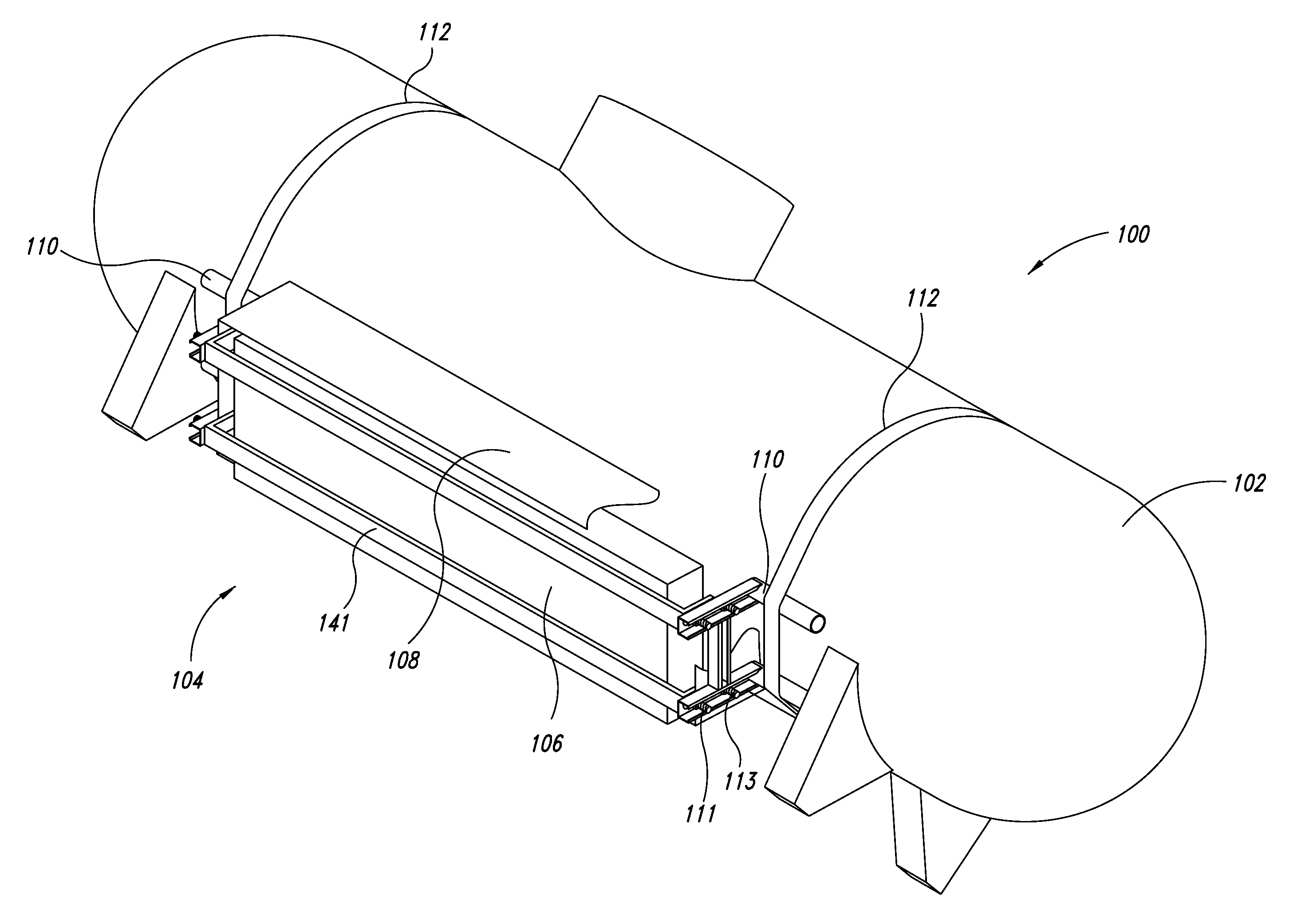
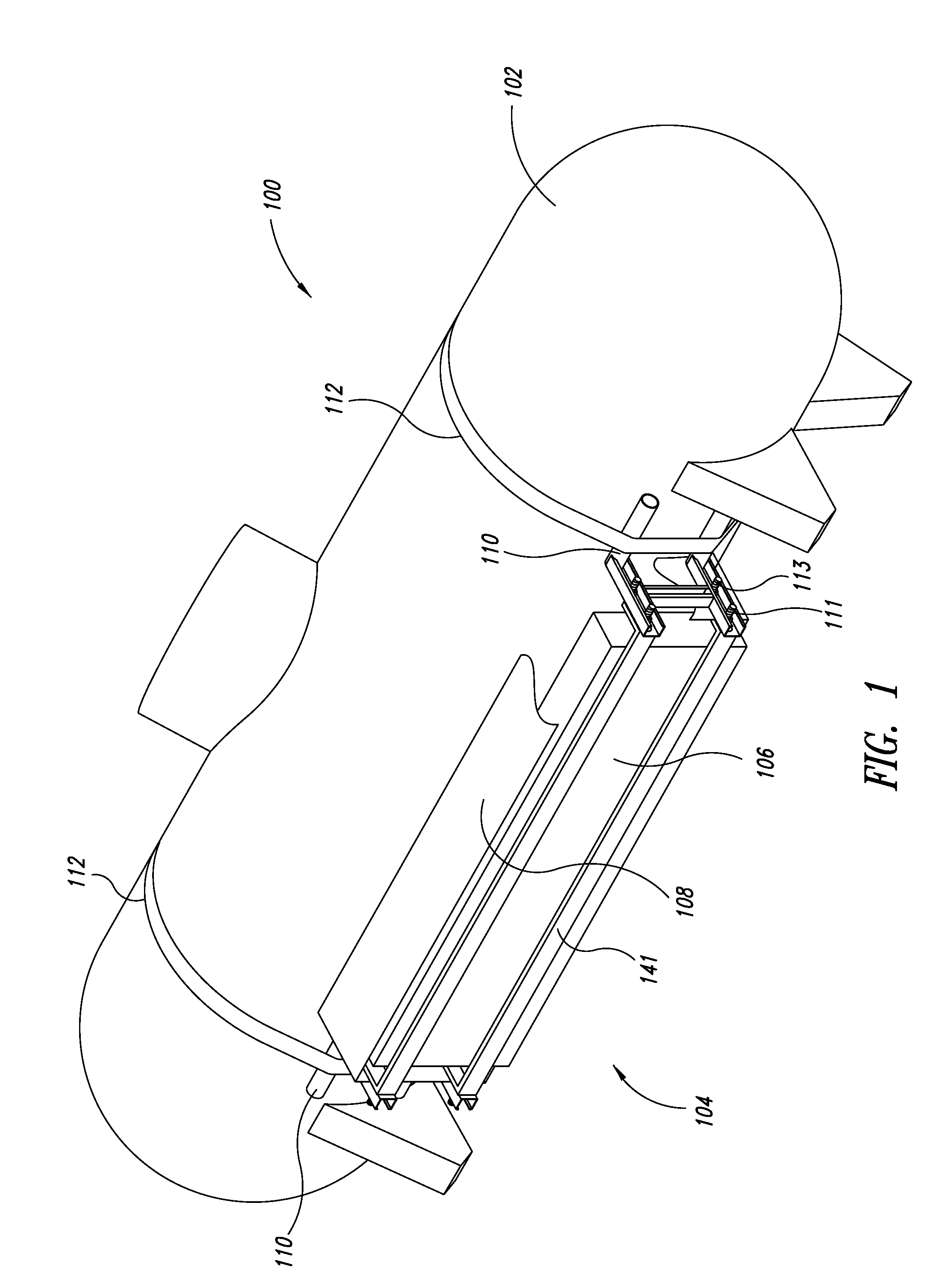
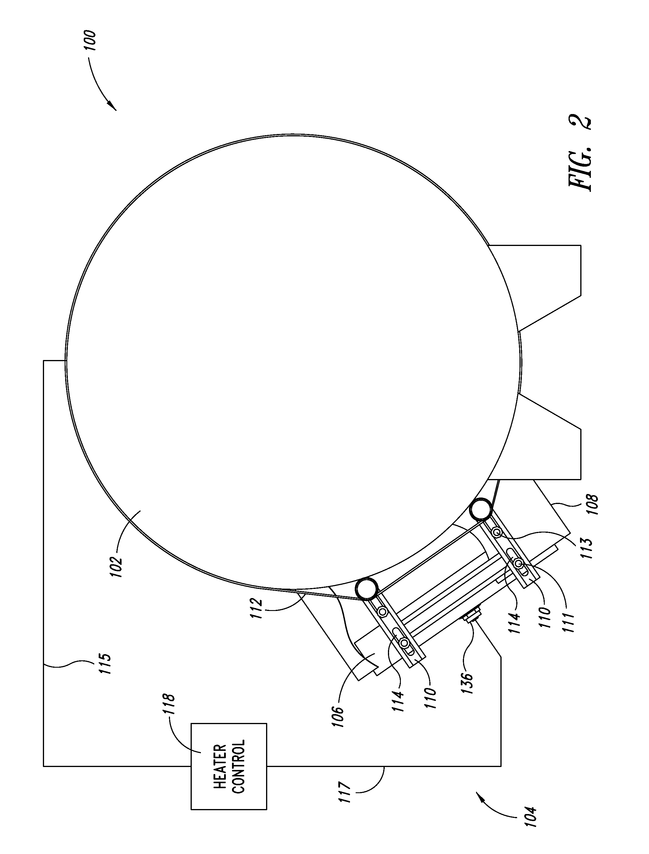
[0040]FIGS. 1 and 2 show an LPG storage system 100 according to an embodiment, which includes an LPG tank 102 and a catalytic tank heater system 104. The heater system 104 includes a catalytic heater element 106, a heater control 118, a shroud 108, mounting brackets 141, support frames 110, and straps 112. The support frames 110 are coupled to the tank 102 by the straps 112. The catalytic element 106 is coupled to the mounting brackets 141, which extend between the support frames 110, and are coupled thereto by first fasteners 111 via slot apertures 114 of the support frames. The slot apertures 114 permit adjustment of the position of the catalytic element 106 relative to the wall of the tank 102, to provide for appropriate air circulation and transfer of radiant heat from the element to the tank. The support frames 110 hold the catalytic element 106 spaced from and facing the wall of the tank. Along a line where the catalytic element 106 lies closest to the tank, the distance betwe...


PUM


Abstract

A catalytic tank heater includes a catalytic heating element supported on an LPG tank by a support structure that holds the element in a position facing the tank. Vapor from the tank is provided as fuel to the heating element, and is regulated to increase heat output as tank pressure drops. The heating element is internally separated into a pilot heater and a main heater, with respective separate fuel inlets. The pilot heater remains in continual operation, but the main heater is operated only while tank pressure is below a threshold. Operation of the pilot heater keeps a portion of the catalyst hot, so that, when tank pressure drops below the threshold, and fuel is supplied to the main heater, catalytic combustion quickly expands from the area surrounding the pilot heater to the remainder of the catalyst.

Description

CROSS-REFERENCE TO RELATED APPLICATION[0001]This application claims the benefit of U.S. Provisional Patent Application No. 61 / 355,463, filed Jun. 16, 2010, which provisional application is incorporated herein by reference in its entirety.BACKGROUND OF THE INVENTION[0002]1. Technical Field[0003]Embodiments described in the present disclosure are directed generally to catalytic heaters and heaters for warming storage tanks containing fluids that are normally gaseous at normal atmospheric pressure and typical ambient temperatures, and in particular to catalytic heaters configured to be coupled to such storage tanks, and including pilot heaters to enable rapid activation of the heaters.[0004]2. Description of the Related Art[0005]A number of fluids that are normally found in gaseous form are commonly stored and transported under pressure as liquids, including, for example, methane, butane, propane, butadiene, propylene, and anhydrous ammonia. Additionally, fuel gasses comprising one or ...

Claims


Application Information

Patent Timeline
Patent Type & Authority Applications(United States)
IPC IPC(8): F24C1/00
CPCF17C13/025F17C7/04F17C2201/0109F17C2201/035F17C2201/054F17C2205/018F17C2221/033F17C2221/035F17C2223/0153F17C2223/0161F17C2225/0123F17C2227/0107F17C2227/0306F17C2227/0386F23C13/02F17C2227/0332
Inventor ZIMMER, GEORGE M.ERVIN, JEFFREY R.KIRBY, MICHAEL J.
Owner ALGAS SDI INT
Learn More