ECG front end and method for acquiring ECG signals

a front end and ecg technology, applied in the field of ecg monitoring, can solve the problems of ineffective defibrillation, inability to detect ecg signals, and inability to achieve a single filter,

Active Publication Date: 2011-12-22
GENERAL ELECTRIC CO
View PDF1 Cites 50 Cited by
  • Summary
  • Abstract
  • Description
  • Claims
  • Application Information

AI Technical Summary

Problems solved by technology

To meet the challenges, the complexity of the front end inevitably increases, if too many compromises are not to be made.
In practice, the ECG measurement electronics needs to be protected from the high voltage pulse of a defibrillator, as the defibrillator pulse may cause permanent damage to the ECG measurement apparatus.
Furthermore, the protection is to be implemented so that the energy of the defibrillator pulse is not shunted by the measurement apparatus, which would lead to ineffective defibrillation.
An example of the contradictory requirements is that the electrosurgery unit requires the use of a filtering capacitor to filter out noise, while the presence of such a filter is not desirable in view of detection of the fast pacemaker spikes or other high frequency signals, such as the excitation signal.
The clamp circuit is normally needed, although it produces additional (low frequency) noise in presence of unfiltered high frequency noise from e.g. an electrosurgery unit.
This translates to high space requirement, cumbersome practical circuitry, and high cost.
Furthermore, increased number of protection resistors results in increased number of parallel input branches, which tends to increase the input impedance imbalance of the front end circuitry.
This, in turn, detracts from the ability of the circuitry to reject common mode noise.

Method used


Image

  • ECG front end and method for acquiring ECG signals
  • ECG front end and method for acquiring ECG signals
  • ECG front end and method for acquiring ECG signals

Examples


Embodiment Construction

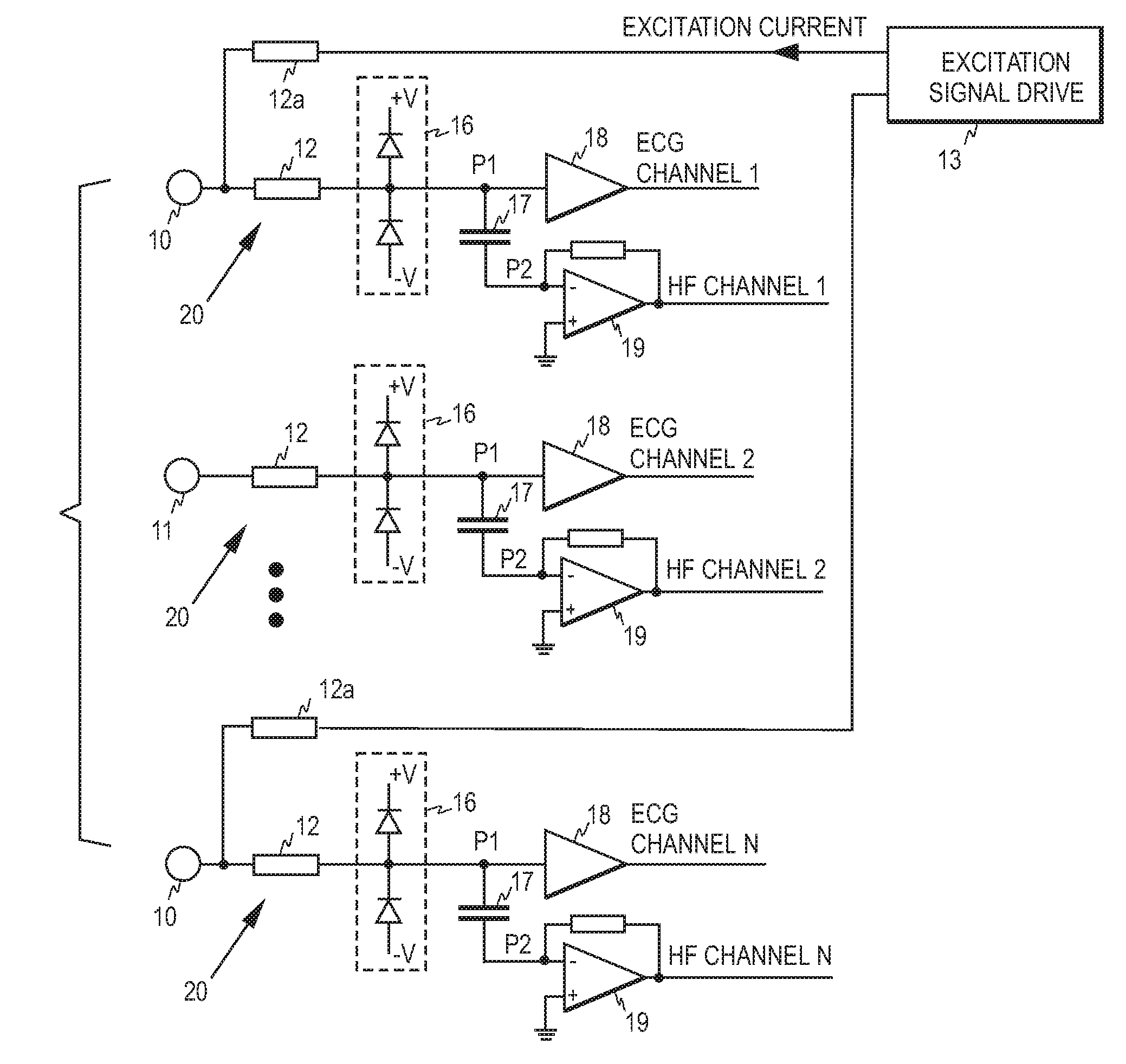
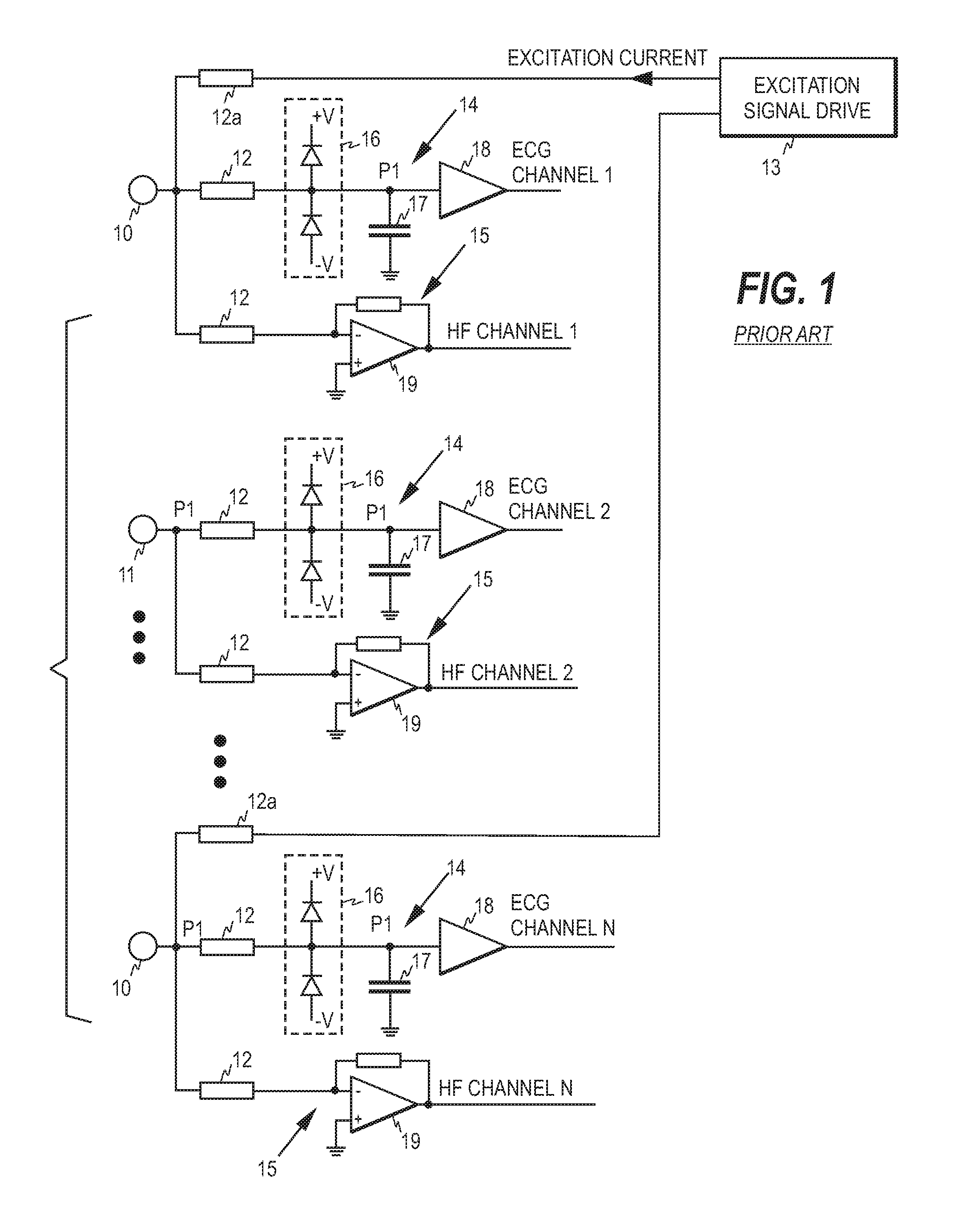
[0014]To demonstrate the basic requirements of an ECG front end, a prior art ECG front end is discussed first. FIG. 1 illustrates an example of a typical prior art ECG front end provided with ECG-derived respiration measurement. The front end is connected to a set of N (N≧3) ECG electrodes comprising typically two outermost electrodes 10 and N−2 middle electrodes 11.

[0015]In this example, the measurement arrangement comprises 2N protection resistors 12 that protect the front end from the high voltage pulses of a defibrillator. In addition, the measurement arrangement comprises two additional protection resistors 12a needed for the respiration measurement. The total number of ECG electrodes is thus 2N+2 in this example. Each outermost electrode 10 is connected to two protection resistors 12 and to one additional protection resistor 12a, while each middle electrode 11 is connected to two protection resistors 12. Due to the ECG-derived respiration measurement, each outermost electrode ...


PUM


Abstract

An ECG front end and a method for acquiring ECG signals are disclosed. The front end comprises a plurality of parallel measurement branches, each measurement branch comprising a protection resistor having a first terminal and a second terminal, wherein the first terminal is connectable to a respective ECG electrode. Each measurement branch comprises a first input amplifier operatively connected to the second terminal of the protection resistor and a capacitor having a first and a second terminal, wherein the first terminal of the capacitor is operatively connected to a point between the first input amplifier and the second terminal of the protection resistor and the second terminal of the capacitor is connected to a virtual ground of a second input amplifier. Each first input amplifier serves as a source of an ECG channel signal and each second input amplifier as a source of high frequency signal components.

Description

BACKGROUND OF THE INVENTION [0001]This disclosure relates generally to electrocardiogram (ECG) monitoring. More particularly, this disclosure relates to implementation of the front end of an ECG monitor.[0002]As is known, the cardiac cycle can be measured non-invasively by attaching small electrodes on the skin of the patient. The voltage differences caused by the heart between the electrodes are measured and recorded to obtain the electrocardiogram (ECG) of the patient. ECG electrodes may also be used to measure a respiratory signal from the patient. For this, a high frequency excitation signal well above the ECG frequencies is normally supplied to the patient. Thus, although filters are used to reduce environmental interferences, certain frequencies higher than the actual ECG frequencies have to be passed to the monitor. In order to be able to record the weak voltages in all circumstances for all patients, the measurement is faced with many challenges. To meet the challenges, the ...

Claims


Application Information

Patent Timeline
Patent Type & Authority Applications(United States)
IPC IPC(8): A61B5/0408A61B5/308
CPCA61B5/7217A61B5/0428A61B5/30A61B5/308
Inventor RANTALA, BORJE
Owner GENERAL ELECTRIC CO
Why Eureka
Try Eureka