Method for predicting initial unbalance in a component

a technology of initial unbalance and component, applied in the direction of mechanical equipment, machines/engines, instruments, etc., can solve the problems of unsatisfactory vibration, damage to the component and the surrounding structure, and the effect of unbalance becoming more pronounced at higher rotational speeds

Inactive Publication Date: 2011-12-29
ROLLS ROYCE PLC
View PDF22 Cites 6 Cited by
  • Summary
  • Abstract
  • Description
  • Claims
  • Application Information

AI Technical Summary

Problems solved by technology

Mass unbalance in rotating components such as wheels, crankshafts, gas turbine engine rotors, etc. can cause undesirable vibration.
Such vibration may cause damage to the component and the surrounding structure.
The effects of unbalance become more pronounced at higher rotational speeds.
Consequently, unbalance is a particular issue in the aerospace industry where components rotate at extremely high speeds.
Furthermore, vibration levels in an aerospace gas turbine engine are not only important from an engine reliability viewpoint but also from a passenger comfort viewpoint.
Therefore, it can be seen that any radial offset of the mass from its centre of mass (i.e. unbalance) results in a large force being exerted on the bearings.
However, blisks are very complex and time consuming to produce, and consequently, the cost per component is very high.
Owing to the complexity of the manufacturing process, there is significant potential for non-conformance in the finished component, and the cost of rejection will again be very high.
Furthermore, it is not possible to balance a blisk by interchanging blades and therefore it is necessary to correct the balance of the blisk using alternative methods.
However, adding weights to balance a blisk is counterproductive since the purpose of a blisk is to save weight.
Furthermore, the weights increase the centrifugal loading on the blisk and can only be located in low stress areas.
This can lead to fretting and erosion.
Also, the weights present a potential cause of Domestic Object Damage (DOD) to the engine, if the connection between a weight and the blisk fails.
This results in the component being heavier than would otherwise be necessary.
Although this ensures that all of the blisks produced can be balanced, the size of the balancing lands is excessive and counteracts the weight saving associated with a blisk.

Method used


Image

  • Method for predicting initial unbalance in a component
  • Method for predicting initial unbalance in a component
  • Method for predicting initial unbalance in a component

Examples


Embodiment Construction

[0029]In an embodiment of the present invention, a prediction of the initial unbalance in a blisk is made using a statistical approach to provide a more realistic reflection of probable unbalance.

[0030]Firstly, it is assumed that each blade used to form the blisk has a mass moment weight which is selected from a normal distribution centred on the expected mass of the blades. However, to remove the most extreme situations, i.e. the maximum possible unbalance described previously, the blades are assumed to have a maximum variation of ±8% from the expected mass. The selected distribution equates to ±3 standard deviations (a) and thus includes 99.7% of blades.

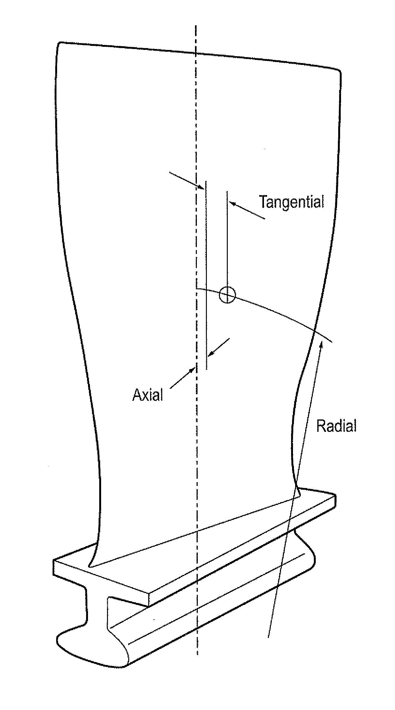
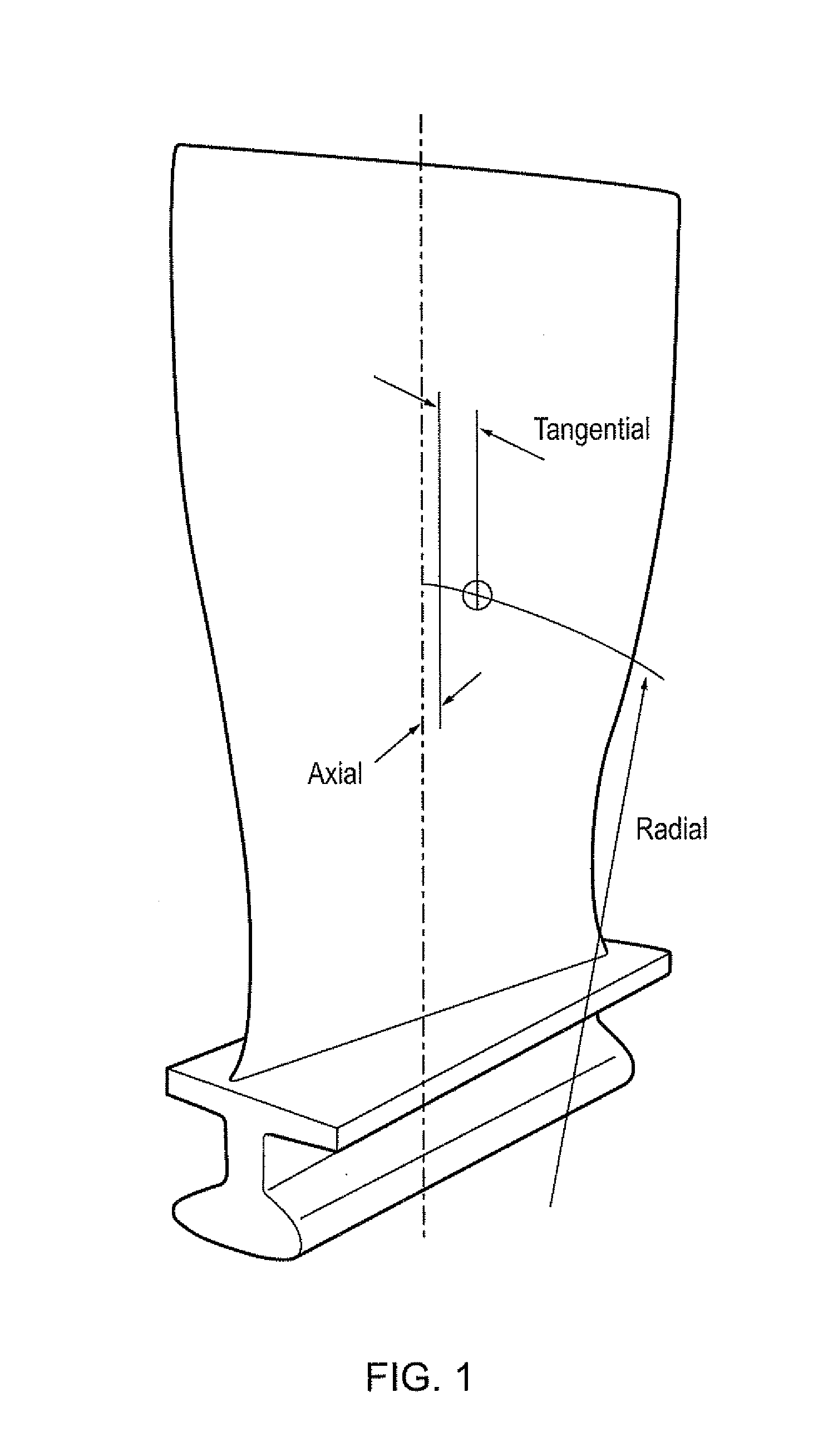
[0031]The normal distribution of the mass moment weights may be a radial, tangential or axial component of the mass moment, as shown in FIG. 1.

[0032]A simulated blisk is formed by selecting a plurality of blades from the distribution and locating the blades at the blade positions around the blisk. The unbalance effect of each blade...


PUM


Abstract

A method for predicting initial unbalance in a component comprising one or more elements, the method comprising: defining a statistical distribution of a mass moment weight of each of the one or more elements; restricting the statistical distribution to a selected range; and calculating an initial unbalance of the component for the restricted distribution of the one or more elements.

Description

[0001]The present invention relates to a method for predicting initial unbalance in a component and particularly, but not exclusively, to a method which allows the weight of the component to be reduced.BACKGROUND[0002]Mass unbalance in rotating components such as wheels, crankshafts, gas turbine engine rotors, etc. can cause undesirable vibration. Such vibration may cause damage to the component and the surrounding structure. Mass unbalance may be corrected by redistributing the mass of the component so as to position the centre of mass at the axis of rotation.[0003]The effects of unbalance become more pronounced at higher rotational speeds. Consequently, unbalance is a particular issue in the aerospace industry where components rotate at extremely high speeds. Furthermore, vibration levels in an aerospace gas turbine engine are not only important from an engine reliability viewpoint but also from a passenger comfort viewpoint.[0004]An unbalanced component exerts a force on its bear...

Claims


Application Information

Patent Timeline
Patent Type & Authority Applications(United States)
IPC IPC(8): G01M1/14
CPCF01D5/027F16F15/32Y02T50/671G01M1/36G01M1/30Y02T50/60G01M1/14G06F30/17G06F30/20
Inventor HARRISON, JOHN M.
Owner ROLLS ROYCE PLC
Why Eureka
Try Eureka