Set of multiaxial force and torque sensor and assembling method

a multi-axial force and torque sensor technology, applied in the field of multi-axial force and torque sensor set, can solve the problems of large amount of handwork in manufacturing, difficult to design programs for such applications using known methods, and inability to provide a means to develop, manufacture and assemble a 6 dof force/torque sensor efficiently and cost-effectively

Inactive Publication Date: 2011-12-29
ABB (SCHWEIZ) AG
View PDF6 Cites 61 Cited by
  • Summary
  • Abstract
  • Description
  • Claims
  • Application Information

AI Technical Summary

Problems solved by technology

Moreover, in many cases, the designing of programs for such applications is difficult using known methods even though 6 DOF force / torque sensors are used to make direct interaction between human beings and robots possible during calibration, programming and program editing.
Accordingly, known techniques do not provide a means to develop, manufacture and assemble a 6 DOF force / torque sensor efficiently and cost-effectively.
This known multiaxial force sensor is highly accurate, but it needs a large amount of handwork in manufacturing.
This causes high cost and limits the achievable production volume.
The application of strain gauges via adhesive bonding needs much care, as they have to be applied to varying sides of complex 3-dimensional metal structures.
The precision of the resulting measurement depends considerably on the accurate orientation of the strain gauges, and even with mounting aids, the handmade assembly is a slow and moderately precise process causing significant efforts.
Based on this state of the art it is an object of the disclosure to provide for multiaxial force and / or torque sensors in a definite arrangement in particular for use for robot control and a method for assembling the respective sensors which is less expensive than with the state of the art, since multiaxial force-torque sensors made with state-of-the art strain gauge technology are high-precision, but complex and very expensive products since the typical design requires a large amount of handwork in production.

Method used


Image

  • Set of multiaxial force and torque sensor and assembling method
  • Set of multiaxial force and torque sensor and assembling method
  • Set of multiaxial force and torque sensor and assembling method

Examples


Embodiment Construction

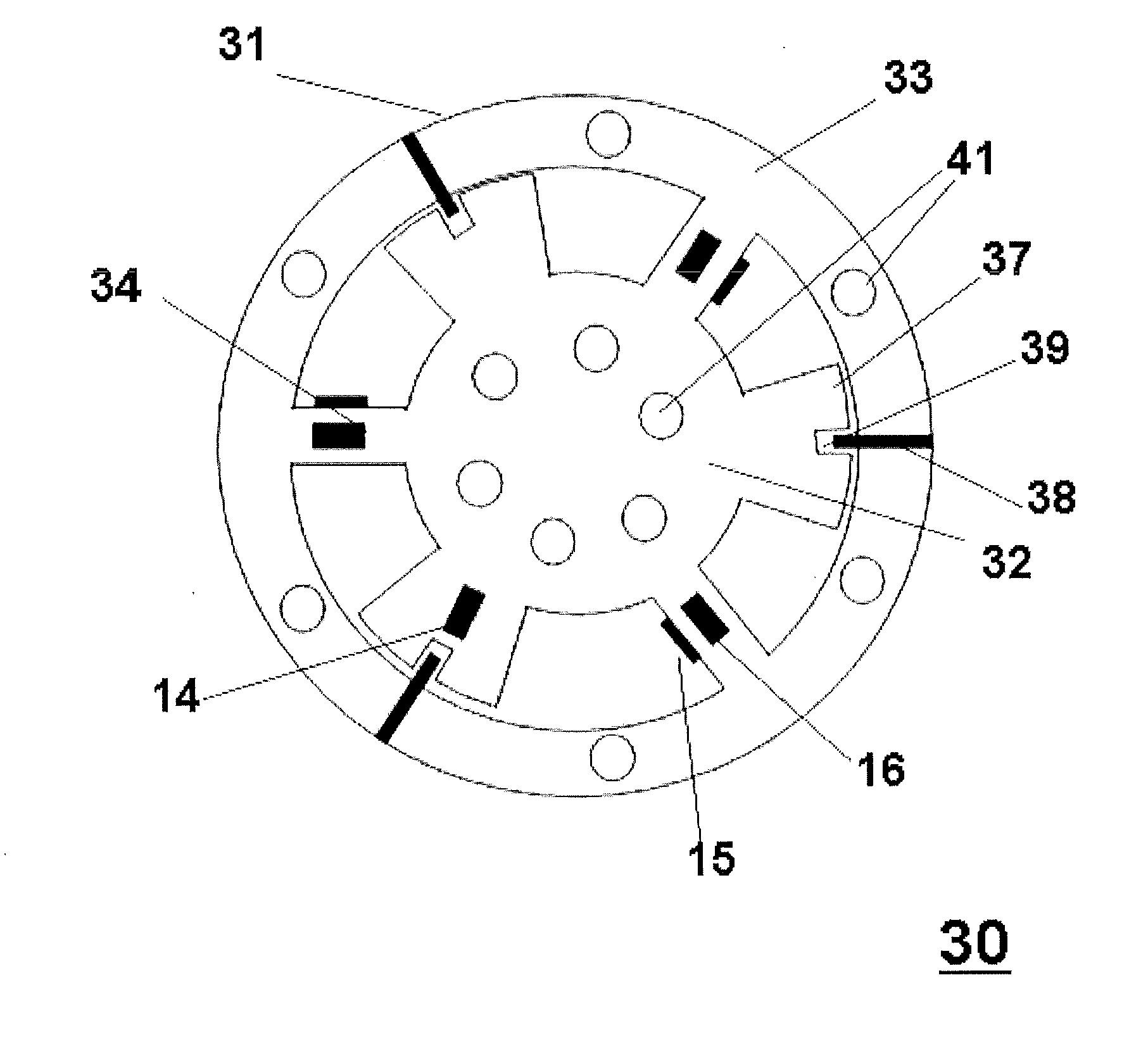
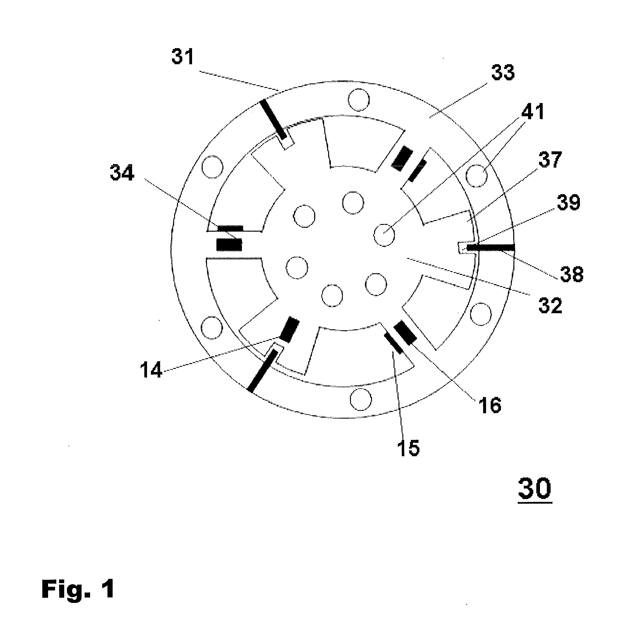
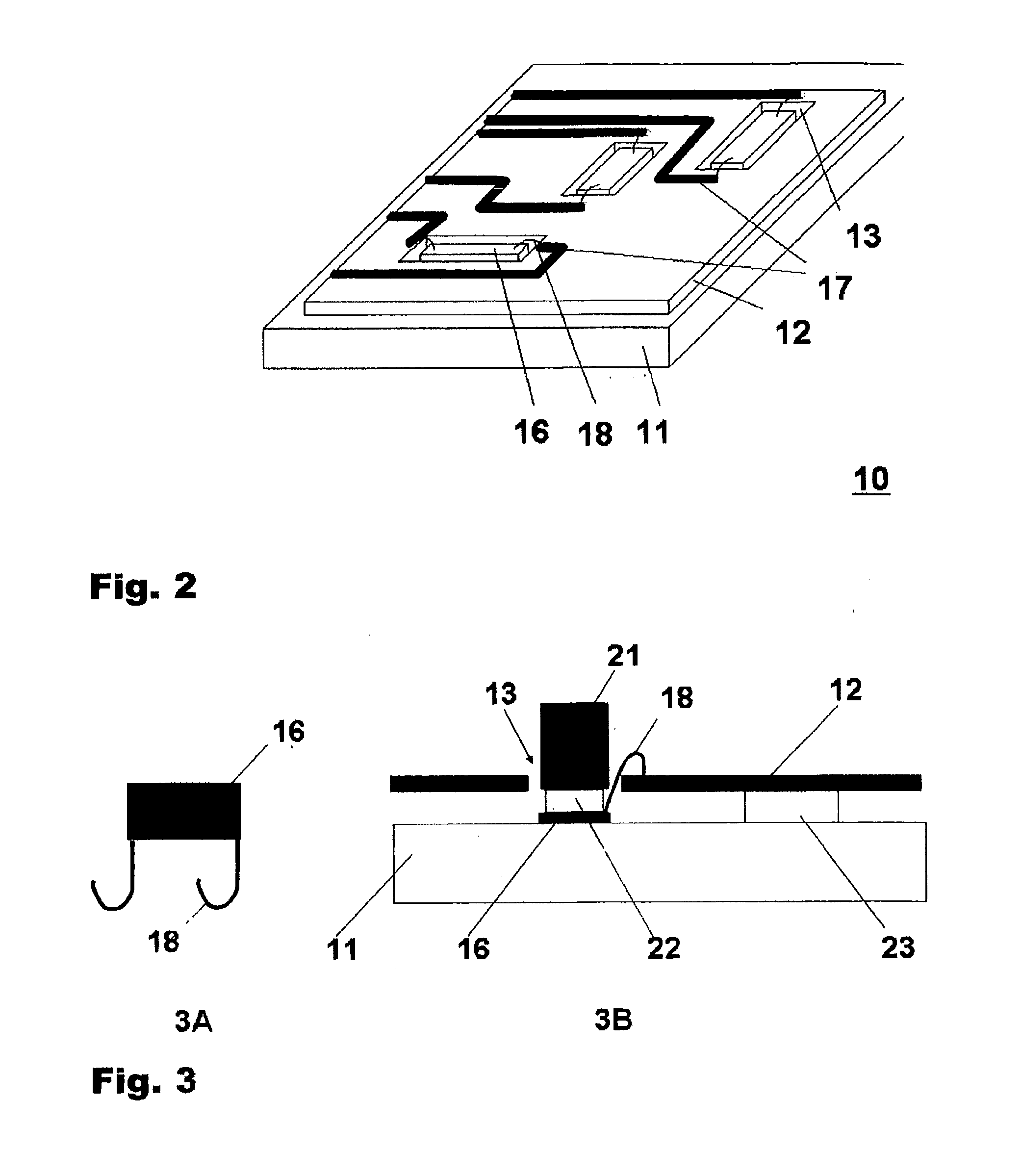
An exemplary embodiment of the present disclosure provides a multiaxial force / torque sensor assembly which includes a set of at least two force sensors each being made of strain gauges. Each of the strain gauges are arranged at a definite angle relative to each other and are each being fixed to a transducer body, which can be a metal plate, for example, and which is laminated with a printed circuit board (PCB). The printed circuit board includes clearances for each strain gauge with associated electronic components and wiring located on the remaining area of the printed circuit board, which, when the transducer body is applied to a structural element, will monitor compressive and tensile stresses in those axes corresponding to the angles of the sensors.

According to an exemplary embodiment of the present disclosure, the printed circuit board can be made of a flexible material. With such a flexible printed circuit board, it is possible to join several transducer modules. Such a flexib...


PUM

PropertyMeasurementUnit
rotationaaaaaaaaaa
angleaaaaaaaaaa
distanceaaaaaaaaaa

Abstract

A multiaxial force/torque sensor assembly and method for assembling such a sensor assembly are disclosed. The sensor assembly includes a set of at least two sensors each being made of strain gauges, which are each arranged at a definite angle and distance relative to each other and which are each fixed to a transducer body, which is mechanical contact with a printed circuit board. The printed circuit board includes clearances for each strain gauge as well as associated electronic components and wiring located on the remaining area of the printed circuit board which will monitor compressive and tensile stresses in the measurement directions of the sensors. The method includes positioning the strain gauges on the plane measurement surface of a transducer body in a definite arrangement; fixing the strain gauges to the transducer body by means of adhesives, and connecting the strain gauges to respective conductors by means of electrically bonding.

Description

FIELDThe present disclosure relates to a set of multiaxial force and torque sensors, and to a method of assembling such sensors. More particularly, the present disclosure relates to multiaxial force sensors made with strain gauges, and to a method of assembling such sensors.BACKGROUND INFORMATIONForce and torque sensors having six degrees of freedom (6 DOF) are used for robot control in most applications involving an interaction between a tool and a work object. Applications of such tools can include assembling, grinding, deburring, drilling, milling, machine tending, laser welding, sheet bending, mechanical testing, etc.Moreover, in many cases, the designing of programs for such applications is difficult using known methods even though 6 DOF force / torque sensors are used to make direct interaction between human beings and robots possible during calibration, programming and program editing.Accordingly, known techniques do not provide a means to develop, manufacture and assemble a 6 ...

Claims


Application Information

Patent Timeline
Patent Type & Authority Applications(United States)
IPC IPC(8): G01L1/22H05K13/00
CPCY10T29/49396G01L3/1457H01L2224/48091H01L2924/00014H01L2224/45099
Inventor KRIPPNER, PETERSZASZ, PAULWETZKO, MANFREDBROGARDH, TORGNY
Owner ABB (SCHWEIZ) AG
Why Eureka
Try Eureka