

Transfer print structure and the manufacturing method thereof
a technology of transfer print and manufacturing method, which is applied in the direction of printing form reproduction, optical elements, instruments, etc., can solve the problems of uneasy region of color ink layer, and achieve the effect of enhancing the adhesion force between the color ink layer and the acceptor substra
- Summary
- Abstract
- Description
- Claims
- Application Information
AI Technical Summary
Benefits of technology
Problems solved by technology
Method used
Image

Examples
first embodiment
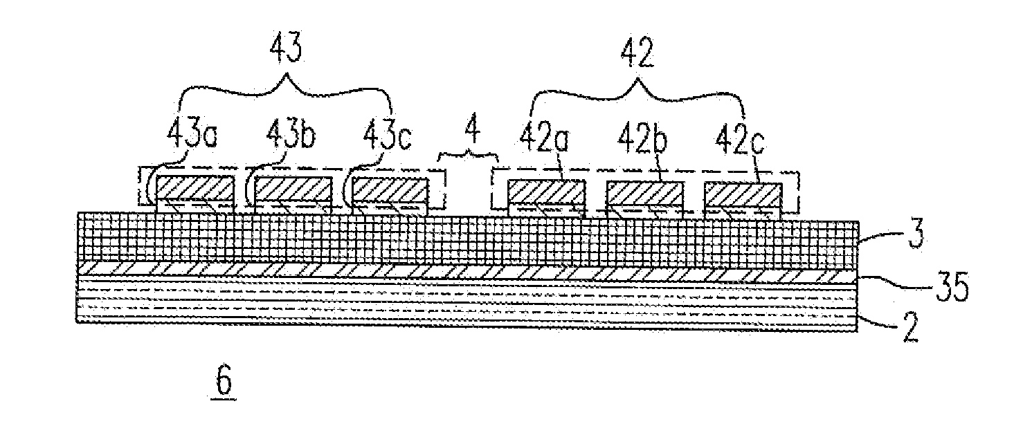
[0039]In accordance with the present invention, a transfer print structure is provided. The transfer print structure comprises a substrate; a color ink layer including a functional region; and an adhesive device combining the functional region with the substrate.
[0040]Preferably, the adhesive device is an adhesive layer disposed between the functional region and the substrate, and is an adhesive material formed in one piece with the functional region to adhere to the substrate.
[0041]Preferably, the adhesive device comprises a material being one selected from a group consisting of an epoxy, a poly-urethane, a cyanamide acrylic and a silicon resin.
[0042]Preferably, the color ink layer further comprises a nonfunctional region.
[0043]Preferably, the color ink layer is a color photo resist layer.
[0044]Preferably, the transfer print structure further comprises a heat conversion layer, wherein the color ink layer is disposed between the heat conversion layer and the adhesive device.
[0045]Pr...
second embodiment
[0052]In accordance with the present invention, a method for manufacturing a transfer print structure is provided. The method comprises steps of (a) adhering a first substrate to a second substrate; (b) providing a color ink layer including a functional region and a nonfunctional region; and (c) adhering the functional region to the second substrate.
[0053]Preferably, the method further comprises following steps after the step (c): (d) separating the nonfunctional region from the second substrate; and (e) adhering a protecting film to the functional region.
[0054]Preferably, the method further comprises a step of selectively irradiating the functional region to make the functional region be transfer-printed onto the second substrate.
[0055]Preferably, the transfer print structure has an adhesive force formed between the functional region and the second substrate, and the adhesive force is enhanced by the step (c).
[0056]Preferably, the transfer print structure further comprises a heat c...
third embodiment
[0057]In accordance with the present invention, a method for manufacturing a transfer print structure is provided. The method comprises steps of (a) providing a first substrate; (b) providing a color ink layer including a functional region; and (c) adhering the functional region to the first substrate.
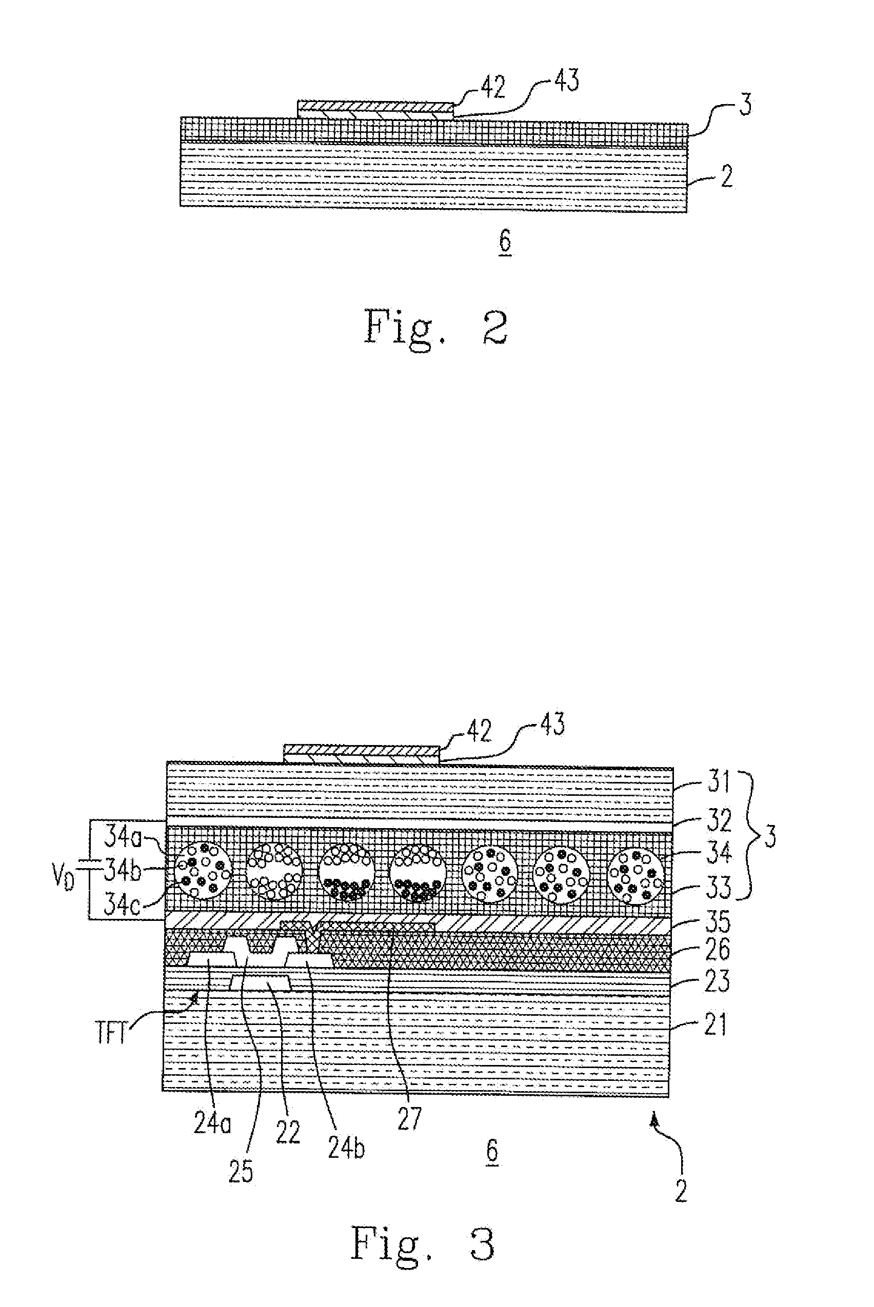
[0058]Preferably, the method further comprises steps of (d) providing a second substrate including a pixel electrode; and (e) adhering the first substrate to the second substrate by aligning the pixel electrode with the functional region.
[0059]Based on the above, the present invention effectively solves the problems and drawbacks in the prior art, and thus it fits the demand of the industry and is industrially valuable.
PUM
| Property | Measurement | Unit |
|---|---|---|
| thickness | aaaaa | aaaaa |
| semiconductor | aaaaa | aaaaa |
| adhesive force | aaaaa | aaaaa |
Abstract
Description
Claims
Application Information