Sensing magnet assembly, rotor position sensing apparatus, and motor including same
a sensing magnet and assembly technology, applied in the direction of instruments, windings, transportation and packaging, etc., can solve the problems of reduced adhesive force, weak coupling force between the sensing magnet and the sensing plate which are coupled using the adhesive, and reduced adhesive force, so as to increase the coupling force between the sensing magnet and the sensing plate, the effect of increasing the adhesive force between the magnet and the plate and increasing the coupling for
- Summary
- Abstract
- Description
- Claims
- Application Information
AI Technical Summary
Benefits of technology
Problems solved by technology
Method used
Image
Examples
first embodiment
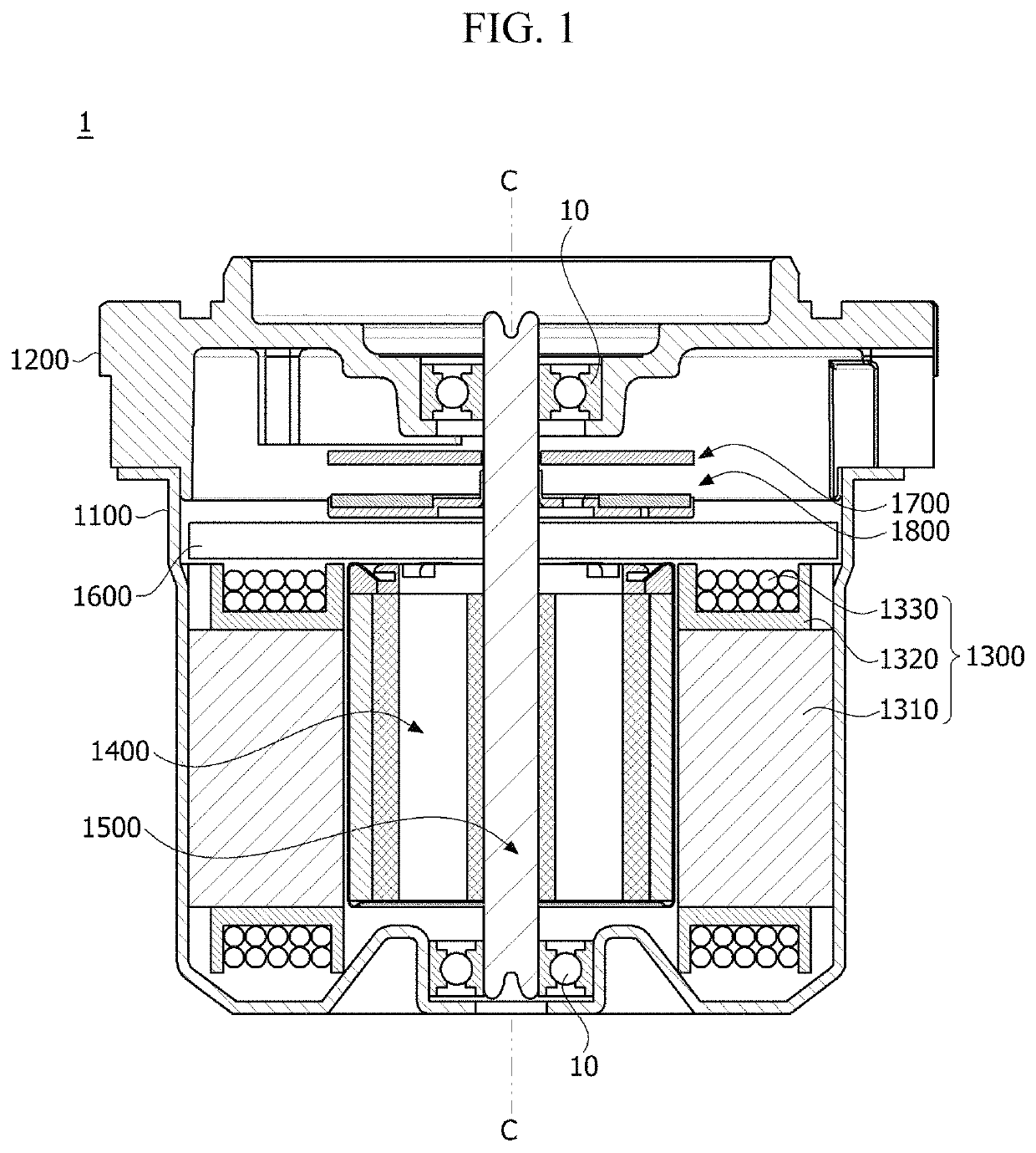
[0071]FIG. 1 is a view illustrating a motor according to a first embodiment.
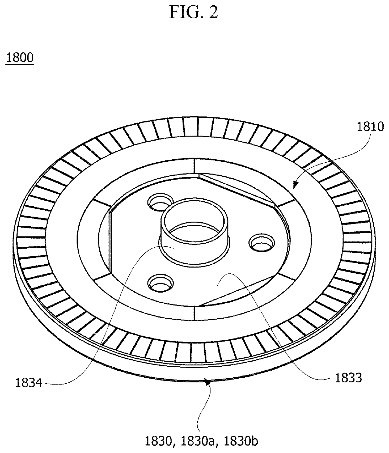
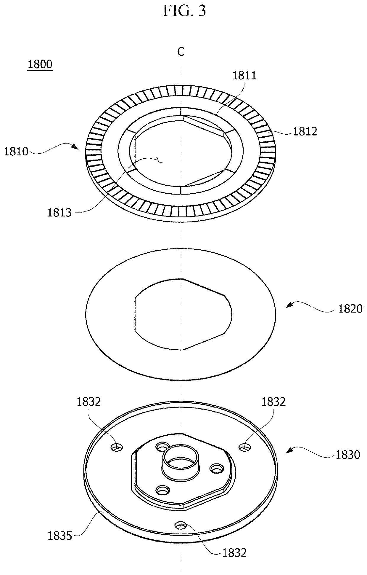
[0072]Referring to FIG. 1, a motor 1 according to the first embodiment may include a housing 1100 in which an opening is formed at one side thereof, a cover 1200 disposed on the housing 1100, a stator 1300 disposed in the housing 1100, a rotor 1400 disposed inside the stator 1300, a shaft 1500 which rotates with the rotor 1400, a busbar 1600 disposed on the stator 1300, a sensor unit 1700 configured to detect rotation of the rotor 1400 and the shaft 1500, and a sensing magnet assembly 1800 according to an embodiment. Here, the sensor unit 1700 and the sensing magnet assembly 1800 may be referred to as a rotor position sensing apparatus.
[0073]The motor 1 may be a motor used in an electronic power steering system (EPS). The EPS supplements a steering force with a driving force of the motor to secure turning stability and provide a quick restoring force so that a driver can safely drive.
[0074]The housing 1100 a...
second embodiment
[0151]FIG. 9 is a conceptual view illustrating a motor according to a second embodiment. Referring to FIG. 9, a motor 2 according to a second embodiment may include a shaft 2100, a rotor 2200, a stator 2300, and a rotor position sensing apparatus 2400.
[0152]The shaft 2100 may be coupled to the rotor 2200. When an electromagnetic interaction occurs between the rotor 2200 and the stator 2300 due to a current supplied thereto, the rotor 2200 rotates, and the shaft 2100 rotates in conjunction with the rotor 2200. The shaft 2100 may be connected to a steering shaft of a vehicle and may transmit power to the steering shaft. The shaft 2100 may be supported by bearings.
[0153]The rotor 2200 rotates due to an electrical interaction with the stator 2300.
[0154]The rotor 2200 may include a rotor core 2210 and magnets 2220. The rotor core 2210 may be formed in a shape in which a plurality of plates having a thin circular steel plate shape are stacked or one cylindrical shape. A hole to which the ...
PUM
 Abstract
Description
Claims
Application Information
 - R&D
- Intellectual Property
- Life Sciences
- Materials
- Tech Scout
- Unparalleled Data Quality
- Higher Quality Content
- 60% Fewer Hallucinations
Browse by: Latest US Patents, China's latest patents, Technical Efficacy Thesaurus, Application Domain, Technology Topic, Popular Technical Reports.
© 2025 PatSnap. All rights reserved.Legal|Privacy policy|Modern Slavery Act Transparency Statement|Sitemap|About US| Contact US: help@patsnap.com


