
Photovoltaic (PV) module with improved bus tape to foil ribbon contact

a photovoltaic module and bus tape technology, applied in the field of photovoltaic (pv) modules, can solve the problems of inability to make electrical contact, unreliable, and difficult to meet the needs of the pv module, and achieve the effect of strong, low-resistance electrical conta

Inactive Publication Date: 2011-12-29
FIRST SOLAR INC (US)
View PDF5 Cites 33 Cited by
  • Summary
  • Abstract
  • Description
  • Claims
  • Application Information

AI Technical Summary

Benefits of technology

The present invention provides a photovoltaic module with a plurality of solar cells connected in series. A bus tape is applied to the substrate at each end, and a conductive member, such as a foil ribbon, interconnects the bus tapes. The bus tapes are in electrical contact with the solar cells, and an adhesive conductive material, such as a low temperature solder, ensures a strong, low resistance electrical connection between the components. The invention also includes a method for attaching bus tapes and a conductive ribbon to the substrate, involving applying an insulation material along the substrate, dispensing adhesive conductive material onto the bus tapes, applying a conductive ribbon over the insulation material and adhesive conductive material, and heating the substrate to reflow the solder and make an electrical connection with the bus tapes. The technical effects of the invention include improved electrical performance and durability of the photovoltaic module.

Problems solved by technology

If the junction fails at either location, an open circuit is created and the PV module becomes useless.
Unfortunately, this junction has proven to be problematic.
If the ridge depth is insufficient or the ridges become crushed in the application process, electrical contact is not made or is unreliable.
In addition, failure of the adhesive results in the tape pulling away from the foil ribbon, again resulting in loss of electrical contact.

Method used


Image

  • Photovoltaic (PV) module with improved bus tape to foil ribbon contact
  • Photovoltaic (PV) module with improved bus tape to foil ribbon contact
  • Photovoltaic (PV) module with improved bus tape to foil ribbon contact

Examples


Embodiment Construction

[0020]Reference now will be made in detail to embodiments of the invention, one or more examples of which are illustrated in the drawings. Each example is provided by way of explanation of the invention, not limitation of the invention. In fact, it will be apparent to those skilled in the art that various modifications and variations can be made in the present invention without departing from the scope or spirit of the invention. For instance, features illustrated or described as part of one embodiment, can be used with another embodiment to yield a still further embodiment. Thus, it is intended that the present invention encompass such modifications and variations as come within the scope of the appended claims and their equivalents.

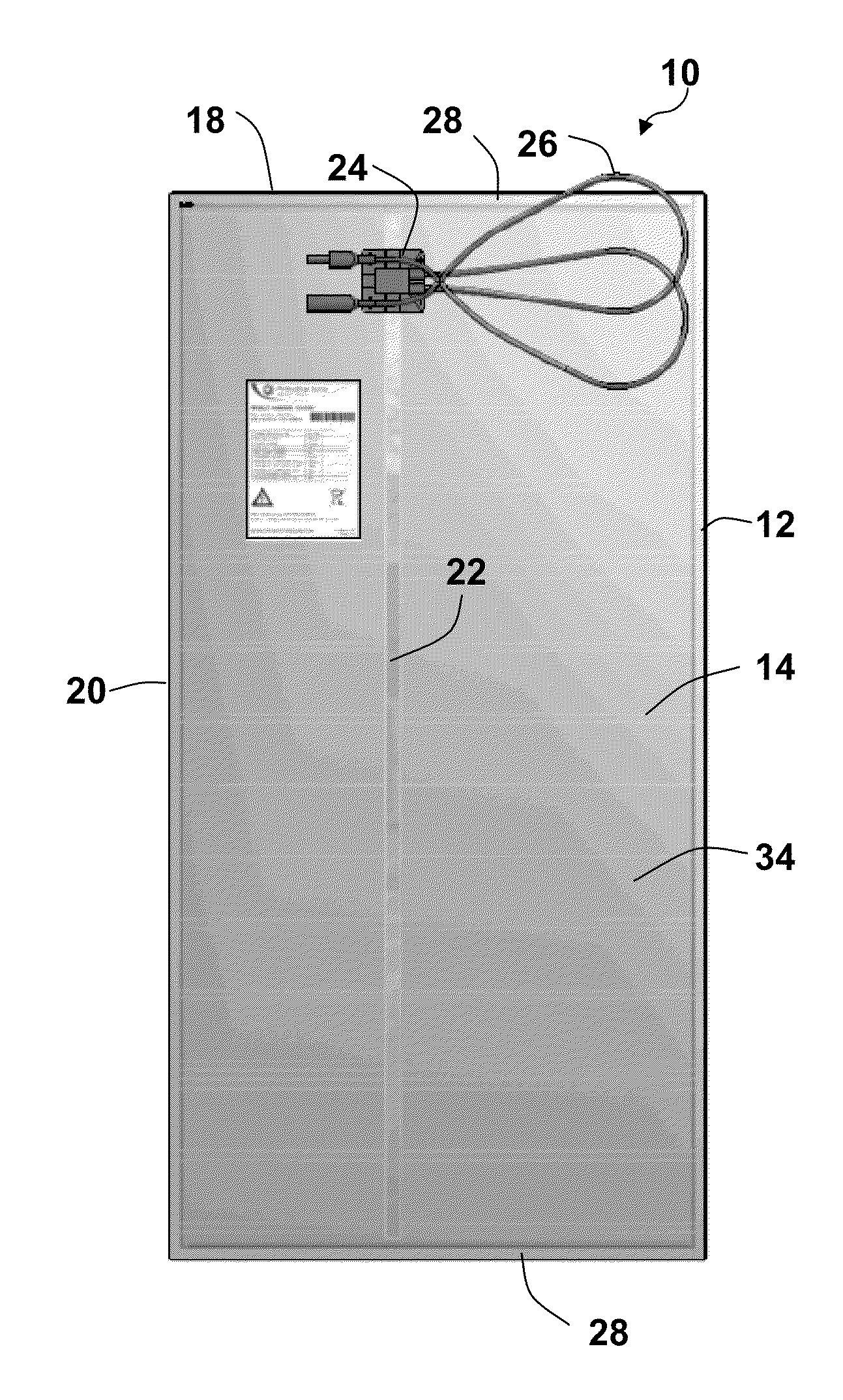
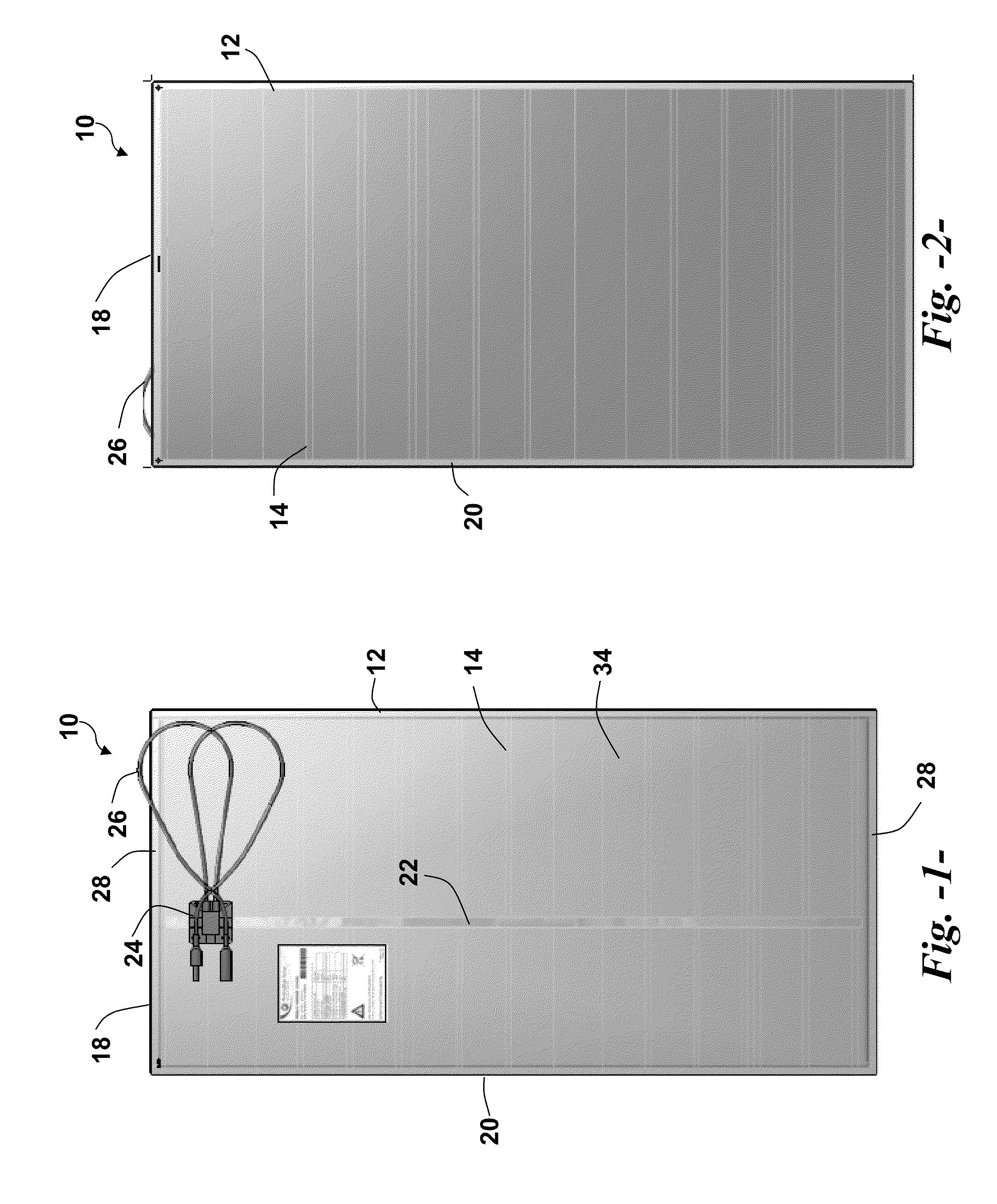
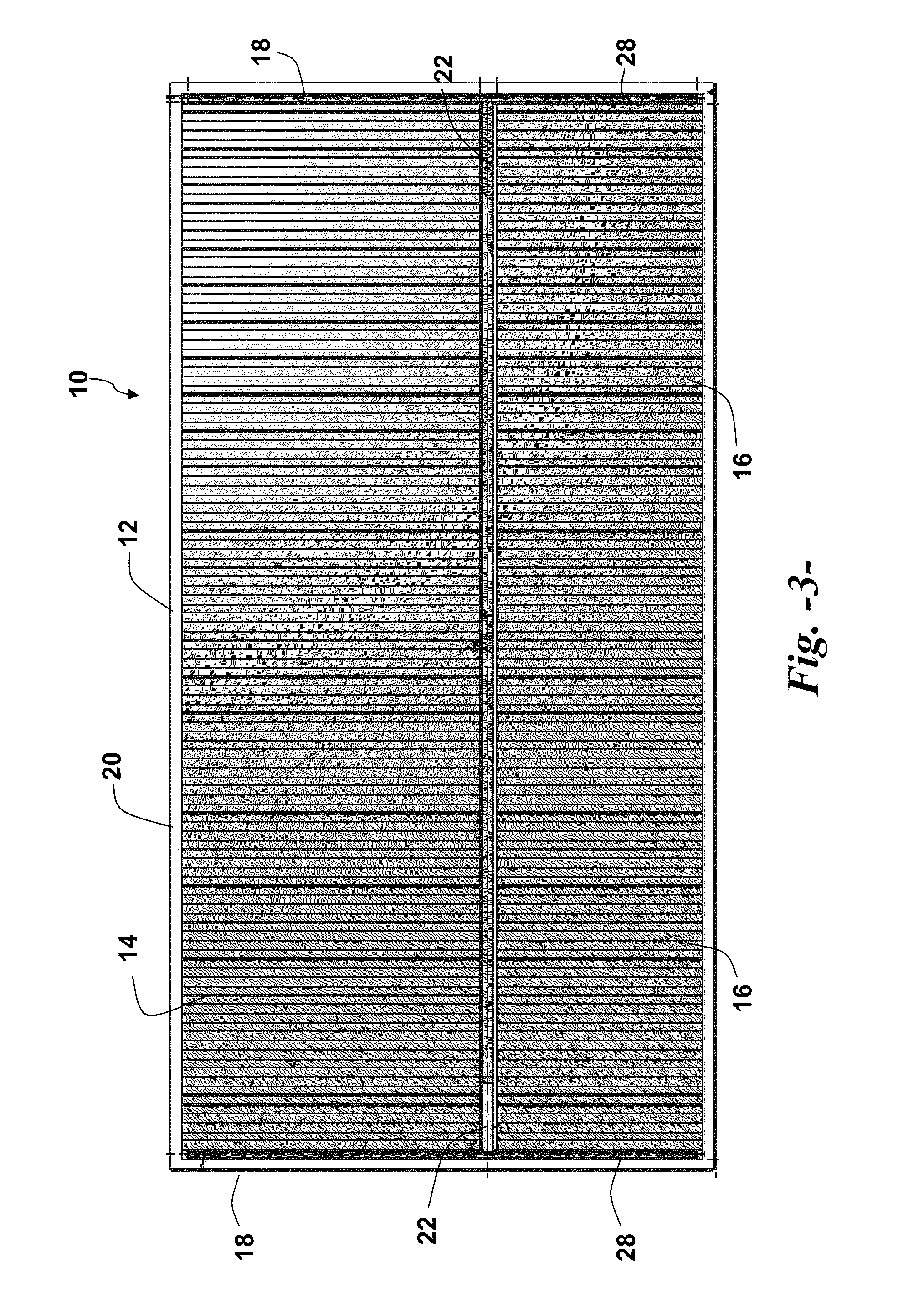
[0021]FIGS. 1 and 2 illustrate a photovoltaic (PV) module 10. FIG. 1 is a view of the back side of the module and FIG. 2 is a view of the front side of the module 10 that is exposed to sunlight for generation of electricity. The module 10 includes a sub...


PUM


Abstract

A photovoltaic (PV) module, and associated method of making, includes a substrate having a plurality of individual serially connected solar cells defined thereon. A bus tape is applied to the substrate generally at each opposite longitudinal end thereof. The bus tapes are applied over the extreme opposite solar cells for collecting the charge generated by the plurality of solar cells. A conductive member, such as a foil ribbon, is connected between the bus tapes and to an intermediate junction box that is configured for delivering the generated charge to an external load or other component. At a point of electrical connection between the bus tapes and the foil ribbon, the bus tapes are disposed beneath the foil ribbon and a conductive adhesive material, such as a solder, is between the foil ribbon and bus tapes.

Description

FIELD OF THE INVENTION[0001]The subject matter disclosed herein relates generally to the photovoltaic (PV) modules, and more particularly to an improved contact between the bus tapes and foil ribbon on PV modules.BACKGROUND OF THE INVENTION[0002]Thin film photovoltaic (PV) modules (also referred to as “solar panels”) are gaining wide acceptance and interest in the industry. The PV modules are conventionally formed by deposition of various semiconductor materials and electrode layers as thin (generally recognized in the art as less than 10 microns) film layers on a glass substrate. The substrate then undergoes various processing steps, including laser scribing processes, to define and isolate individual cells, define a perimeter edge zone around the cells, and to connect the cells in series. These steps result in generation of a plurality of individual solar cells defined within the physical edges of the substrate.[0003]A well known method for collecting the charge from a PV module i...

Claims


Application Information

Patent Timeline
Patent Type & Authority Applications(United States)
IPC IPC(8): H01L31/042H01L31/18
CPCY02E10/50H02S40/34H01L31/0201
Inventor KABADE, RAJENDRA RAMBHAU
Owner FIRST SOLAR INC (US)
Learn More