
Cable edging systems and methods

Inactive Publication Date: 2011-12-29
GOOGLE LLC
View PDF5 Cites 35 Cited by
  • Summary
  • Abstract
  • Description
  • Claims
  • Application Information

AI Technical Summary

Benefits of technology

[0007]Aspects of the invention provide a low-impact, convenient, time-efficient and cost-saving optical fiber deployment technology.

Problems solved by technology

Typically, the drop fiber is buried at least a few inches under the surface, which requires significant effort and time.

Method used


Image

  • Cable edging systems and methods
  • Cable edging systems and methods
  • Cable edging systems and methods

Examples


Embodiment Construction

[0032]Aspects, features and advantages of the invention will be appreciated when considered with reference to the following description of exemplary embodiments and accompanying figures. The same reference numbers in different drawings may identify the same or similar elements. Furthermore, the following description is not limiting; the scope of the invention is defined by the appended claims and equivalents.

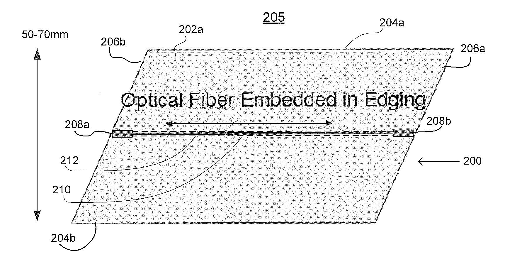
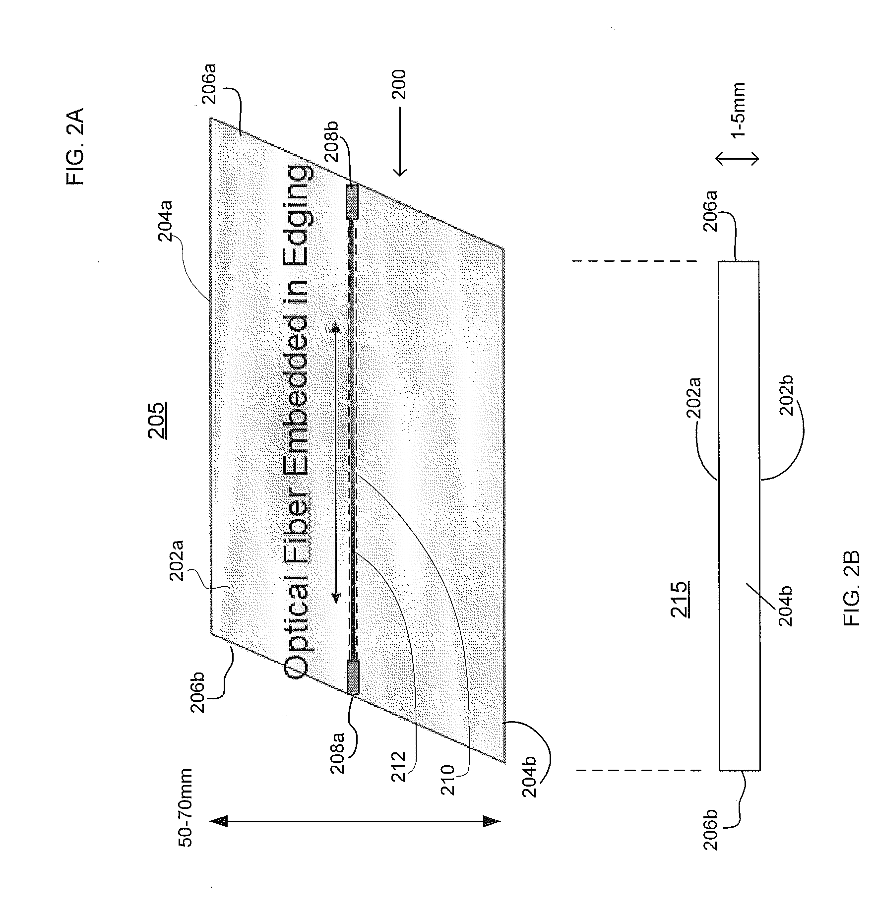
[0033]In accordance with aspects of the invention, a fiber deployment device and method facilitates fiber installation, preferably from a demarcation point to a customer premise. Methods and devices consistent with the present invention enable the placement of fiber-optic cables through embedding fiber optic cable in a thin edging strip and pressing the edging strip into the ground.

[0034]FIG. 2A illustrates a perspective view 205 of an exemplary device 200 to facilitate deploying fiber-optic cables in accordance with embodiments of the invention. The device 200 may include a sub...


PUM

PropertyMeasurementUnit
Distanceaaaaaaaaaa
Distanceaaaaaaaaaa
Lengthaaaaaaaaaa

Abstract

Devices and methods are provided for deploying optical fiber-optic cables or other cables. A general planar device is formed with a conduit disposed along the device. One or more fiber-optic cables or other types of communication cables are inserted through the conduit. The device with the embedded cables is pressed into the ground and can be used to provide high-bandwidth communications to a user's home from a service provider.

Description

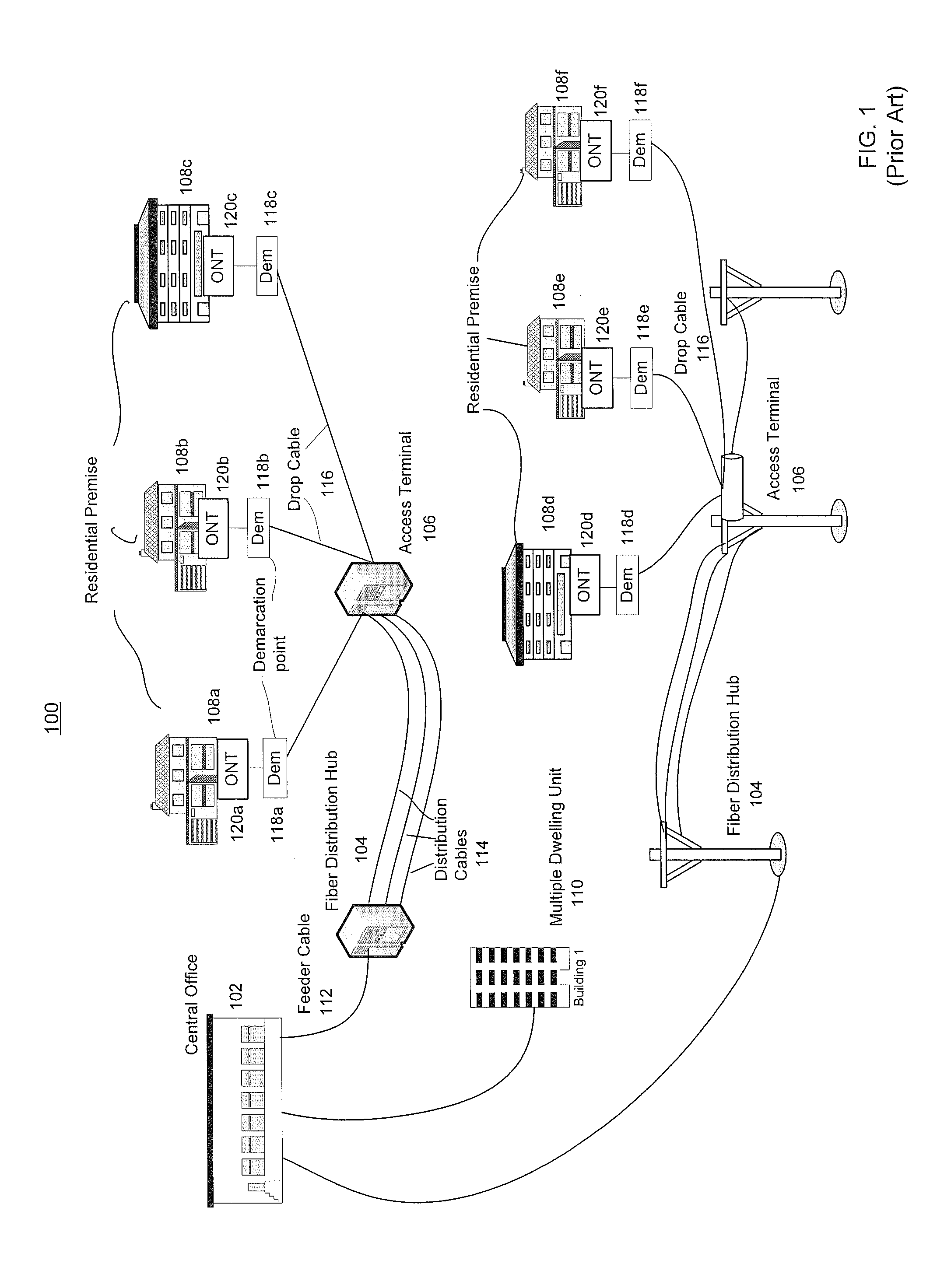
BACKGROUND OF THE INVENTION[0001]1. Field of the Invention[0002]The invention relates generally to a fiber deployment method and device, including installing a fiber-optic cable in a narrow edging strip.[0003]2. Description of Related Art[0004]Fiber-to-the-home or Fiber-to-the-premise (FTTH, FTTP, sometimes collectively known as FTTx) systems are broadband communication solutions that have quickly become a preferred technology for delivering bandwidth-intensive data such as pictures, video and Internet services. Such systems are currently in deployment throughout the U.S. and other parts of the world. There are a number of options for deploying fiber, such as running fiber-optic cable aerially from the existing utility poles, or burying cable straight into the ground or in existing or new ducts.[0005]FIG. 1 illustrates various ways to install fiber optic cables in an FTTx system. The optical fiber running from the Central Office 102 to a Fiber Distribution Hub 104, where optical spl...

Claims


Application Information

Patent Timeline
IPC IPC(8): F16L55/00B23P11/00F16L1/028A01G9/28
CPCG02B6/4459Y10T29/49826G02B6/504
Inventor KELLY, JAMES FINTAN
Owner GOOGLE LLC
Learn More