Pneumatic tire

a pneumatic tire and rubber technology, applied in the field of pneumatic tires, can solve the problems of poor die releasability, easy rubber chipping, adverse effects on braking performance and wear performance, etc., and achieve the effect of improving the releasability of the sipe molding blad

Active Publication Date: 2011-12-29
TOYO TIRE & RUBBER CO LTD
View PDF8 Cites 11 Cited by
  • Summary
  • Abstract
  • Description
  • Claims
  • Application Information

AI Technical Summary

Benefits of technology

[0008]In view of the foregoing circumstances, an object is to provide a pneumatic tire capable of suppressing the movement of a block on the ground contact end side within a shoulder region while improving the die releasability of a sipe molding blade.

Problems solved by technology

When the whole of the bottom part is formed in a waveform shape in such a way, on the occasion in which after vulcanization molding of a tire, a sipe molding blade of a die is removed from a tread part, die releasability is poor, so that a problem such as chipping of rubber is easily caused in the sipe surroundings.
Such defectiveness of die releasability is not substantially problematic with respect to tires with low rubber hardness such as studless tires, whereas it is a serious problem with respect to tires with high rubber hardness such as all-season tires and summer tires.
When the ground contact pressure is locally raised in this way, it may be considered that in the subject portion, collapse of a sipe becomes large, and the movement (deformation) of a block becomes large, whereby a braking performance and a wear performance are adversely affected.
However, according to the foregoing conventional sipe configurations, since the sipe has a fixed shape in the length direction, the collapse of a sipe to be caused due to a local rise of the ground contact pressure on the ground contact end side within such a shoulder region could not be suppressed.

Method used


Image

  • Pneumatic tire
  • Pneumatic tire
  • Pneumatic tire

Examples


first embodiment

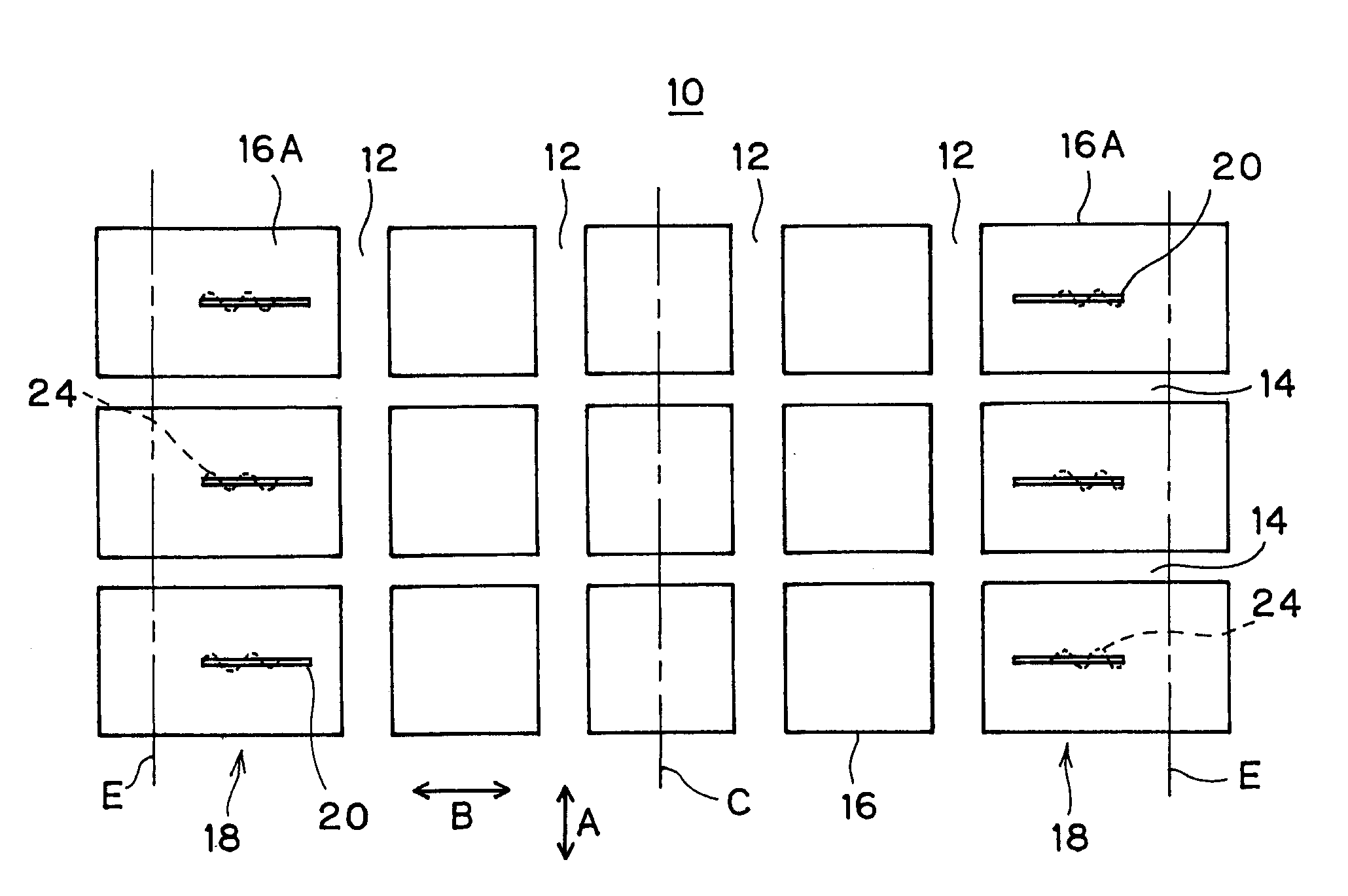
[0021]Though illustration is omitted, a pneumatic tire according to First Embodiment is configured to include a left-and-right pair of a bead part and a sidewall part and a tread part 10 provided between the both sidewall parts so as to connect radial-direction external end parts of the left-and-right sidewall parts to each other. The tire includes a carcass extending over the pair of bead parts. The carcass is composed of at least one carcass ply which extends from the tread part 10 to the sidewall parts and both end parts of which are engaged with an annular bead core embedded in the bead parts, and reinforces each of the foregoing parts. A belt composed of two or more rubber-coated steel code layers is provided on the peripheral side of the carcass in the tread part 10 and reinforces the tread part 10 in the periphery of the carcass.

[0022]As shown in FIG. 1, the tread part 10 is provided with plural longitudinal grooves (main grooves) 12 extending in a straight line in a tire cir...

second embodiment

[0041]FIGS. 5A to 5C are each a view of showing the sipe 20 according to Second Embodiment in each of wear stages. In this exemplary embodiment, the wave number of the waveform sipe portion 24 is increased twice as compared with the foregoing First Embodiment. In this way, the wave number of the waveform sipe portion 24 is not particularly limited, and various modifications can be made. Also, the amplitude and wavelength of the waveform and the like are not particularly limited, and they can be properly set up. With respect to Second Embodiment, other configurations are the same as those in First Embodiment, and the same functions and effects are brought.

third embodiment

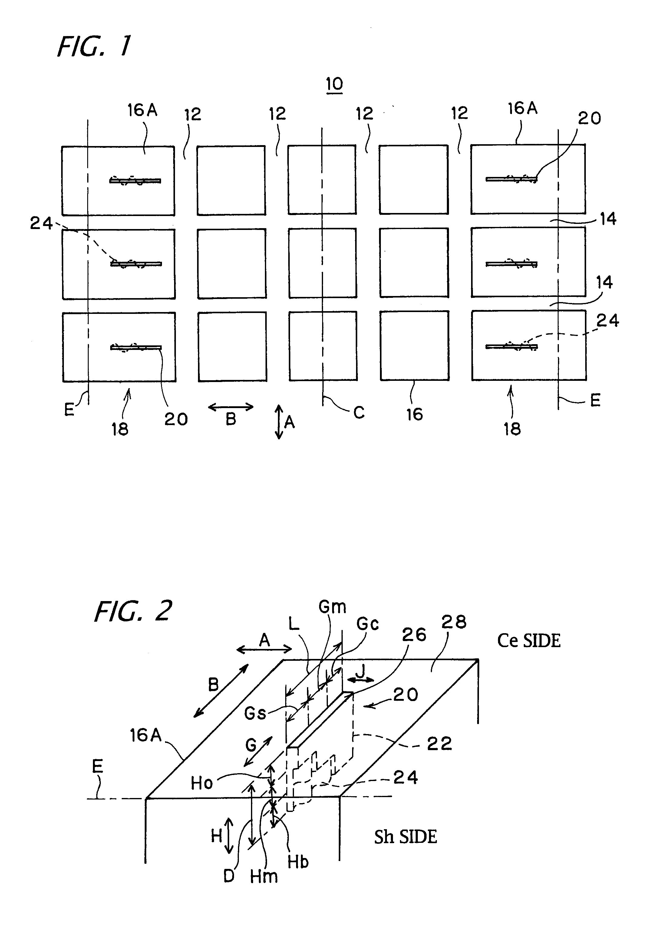
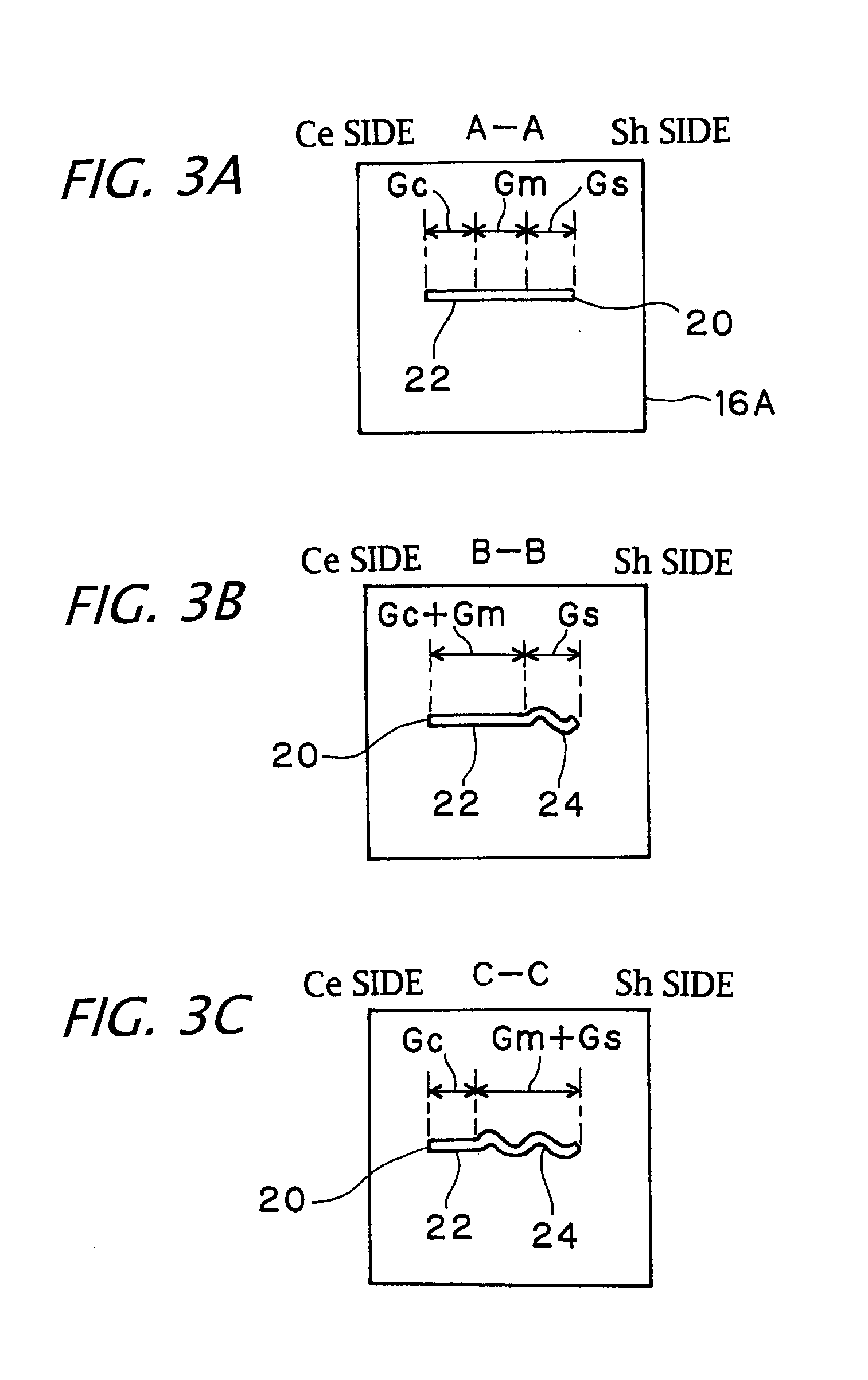
[0042]FIG. 6 is a view showing the sipe 20 according to Third Embodiment and is concerned with a front view showing a sipe wall face and a section in each of wear stages (A-A line section in a first wear stage, B-B line section in a second wear stage, and C-C line section in a third wear stage). In this exemplary embodiment, in an end part on the tread ground contact end side Sh in the sipe length direction G, a region in which the waveform sipe portion 24 is provided over the whole of the sipe depth direction H. On that point, Third Embodiment is different from First Embodiment.

[0043]That is, in this exemplary embodiment, the sipe 20 is divided into four regions in its length direction G, in which a region on the equator side Ce is defined as the inner region Gc, a region adjacent to its ground contact end side Sh is defined as a first central region Gm1, a region adjacent to the ground contact end side Sh of the first central region Gm1 is defined as a second central region Gm2, a...


PUM


Abstract

A sipe extending in a tire width direction is provided in a land part (block) of a tread shoulder region. An inner region on the tire equator side in a length direction of the sipe is formed in a straight sipe portion over the whole of a sipe depth direction. A region on the tread ground contact end side relative to the inner region is divided and provided in the straight sipe portion on the sipe opening side and a waveform sipe portion on the sipe bottom part side in the sipe depth direction.

Description

CROSS-REFERENCE TO RELATED APPLICATIONS[0001]This application is based upon and claims the benefit of priority from the prior Japanese Patent Application No. 2010-142790, filed on Jun. 23, 2010; the entire contents of which are incorporated herein by reference.BACKGROUND OF THE INVENTION[0002]1. Field of the Invention[0003]The present invention relates to a pneumatic tire, and in particular, it relates to a pneumatic tire in which a sipe is formed in a land part of a tread surface.[0004]2. Description of the Related Art[0005]In a land part of a tread surface of a pneumatic tire, for the purpose of enhancing a noise performance, a wet performance or the like, there may be the case where a sipe extending in a tire width direction is provided. Conventionally, in those provided with such a sipe in the width direction, it is known that by forming a waveform sipe in a bottom part of a straight sipe, the sipe shape is changed from a straight line to a waveform form over the middle of wear ...

Claims


Application Information

Patent Timeline
Patent Type & Authority Applications(United States)
IPC IPC(8): B60C11/12
CPCB60C11/11B60C11/12B60C11/1218Y10S152/03B60C11/1204B60C2011/1254B60C2011/1213
Inventor OHASHI, TOSHIYUKI
Owner TOYO TIRE & RUBBER CO LTD
Why Eureka
Try Eureka