Electric Motor

Active Publication Date: 2011-12-29
C & E FEIN
View PDF11 Cites 15 Cited by
  • Summary
  • Abstract
  • Description
  • Claims
  • Application Information

AI Technical Summary

Benefits of technology

[0087]This results in a supporting structure for the contact grid, which can considerably simplify the subsequent handling steps and manufacturing processes. Furthermore, the support structure may have shape elements which simplify the feeding and the assembly of the contact grid. This further improves the suitability for highly automated manufacture. Furthermore, t

Problems solved by technology

However, it has been found that the production and in particular the handling of the grid layers of stamped grids such as these is particularly complex when

Method used


Image

  • Electric Motor
  • Electric Motor
  • Electric Motor

Examples


Example

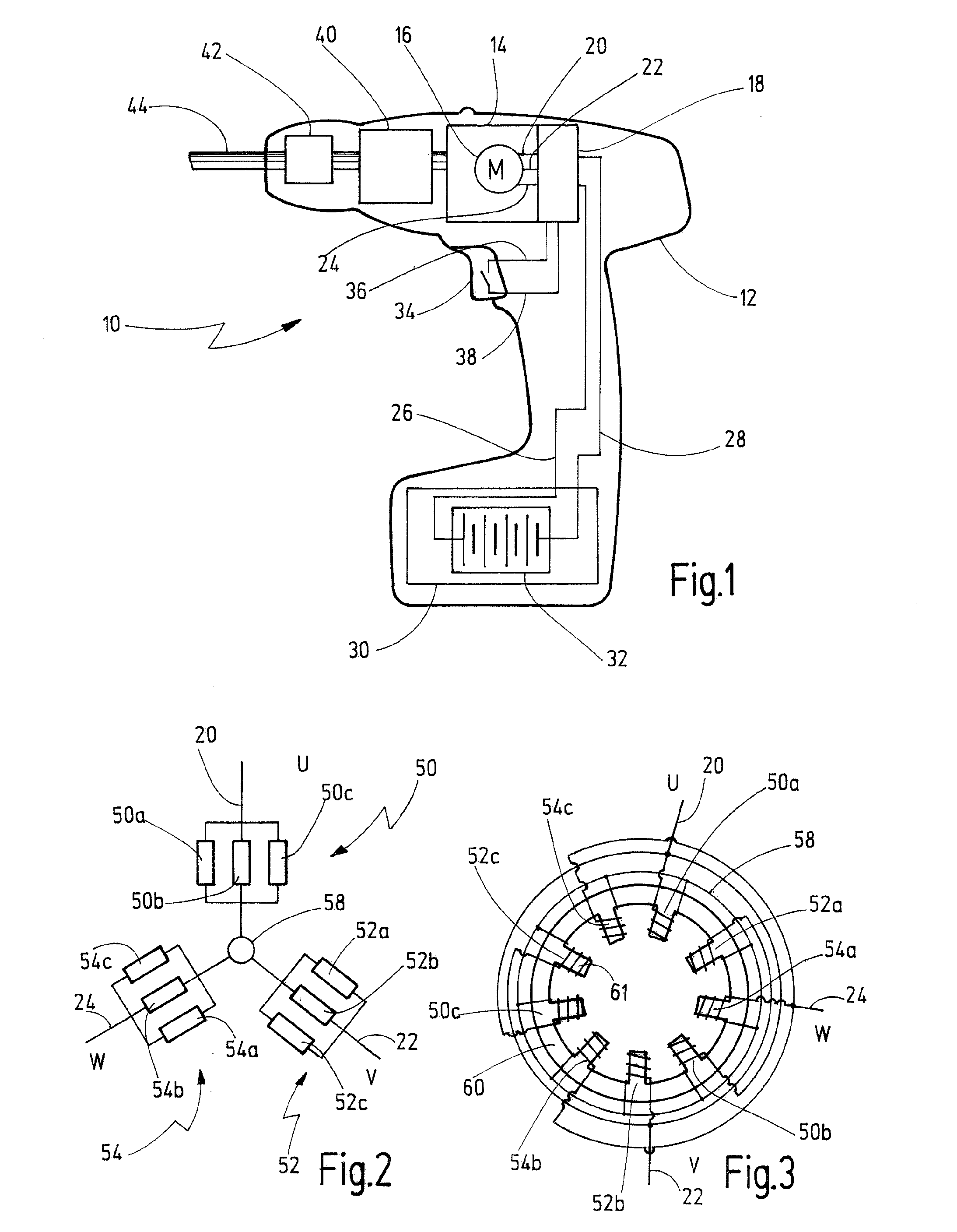
[0105]FIG. 1 schematically illustrates a hand-held tool, which is annotated 10 overall.

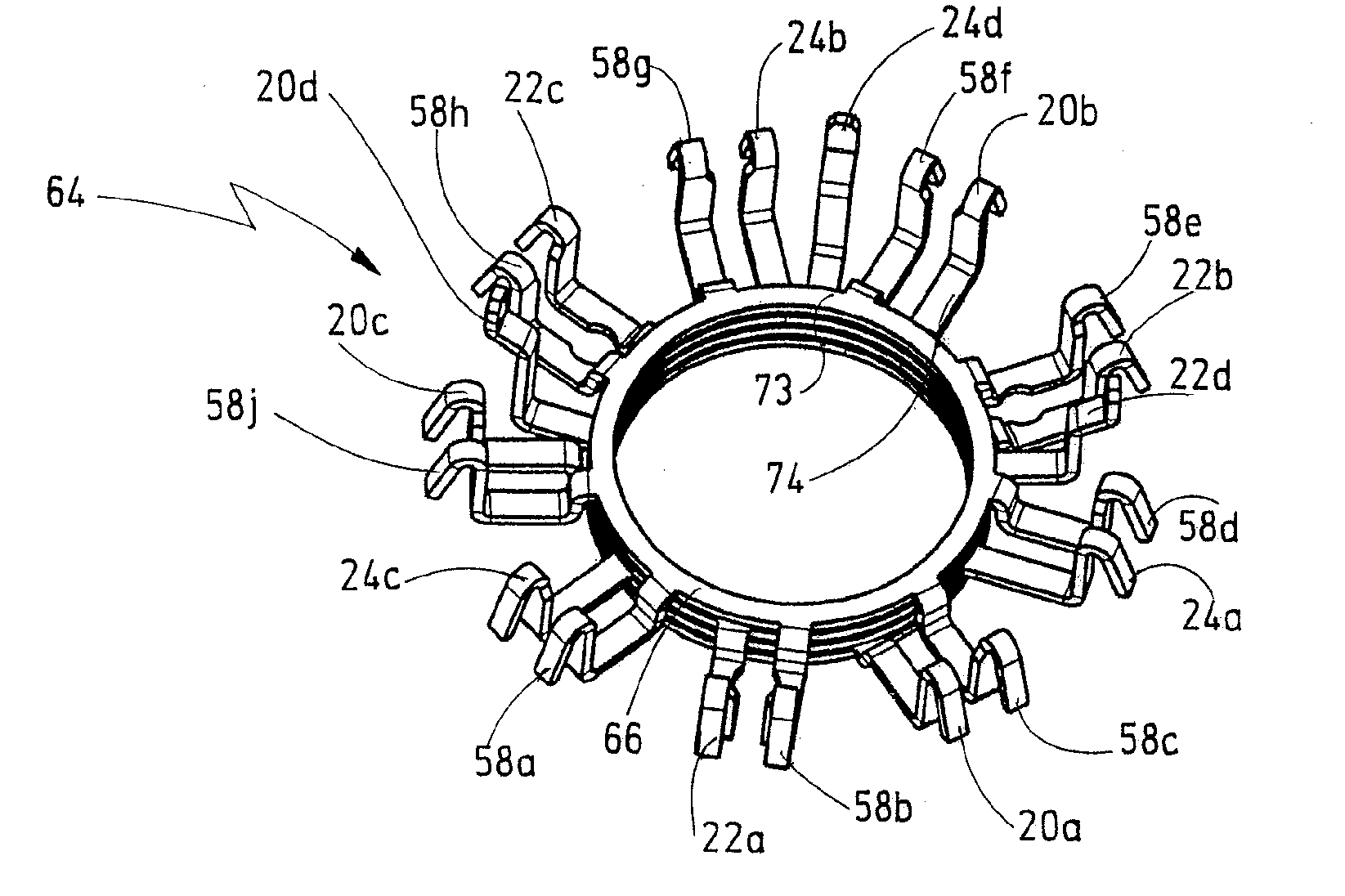
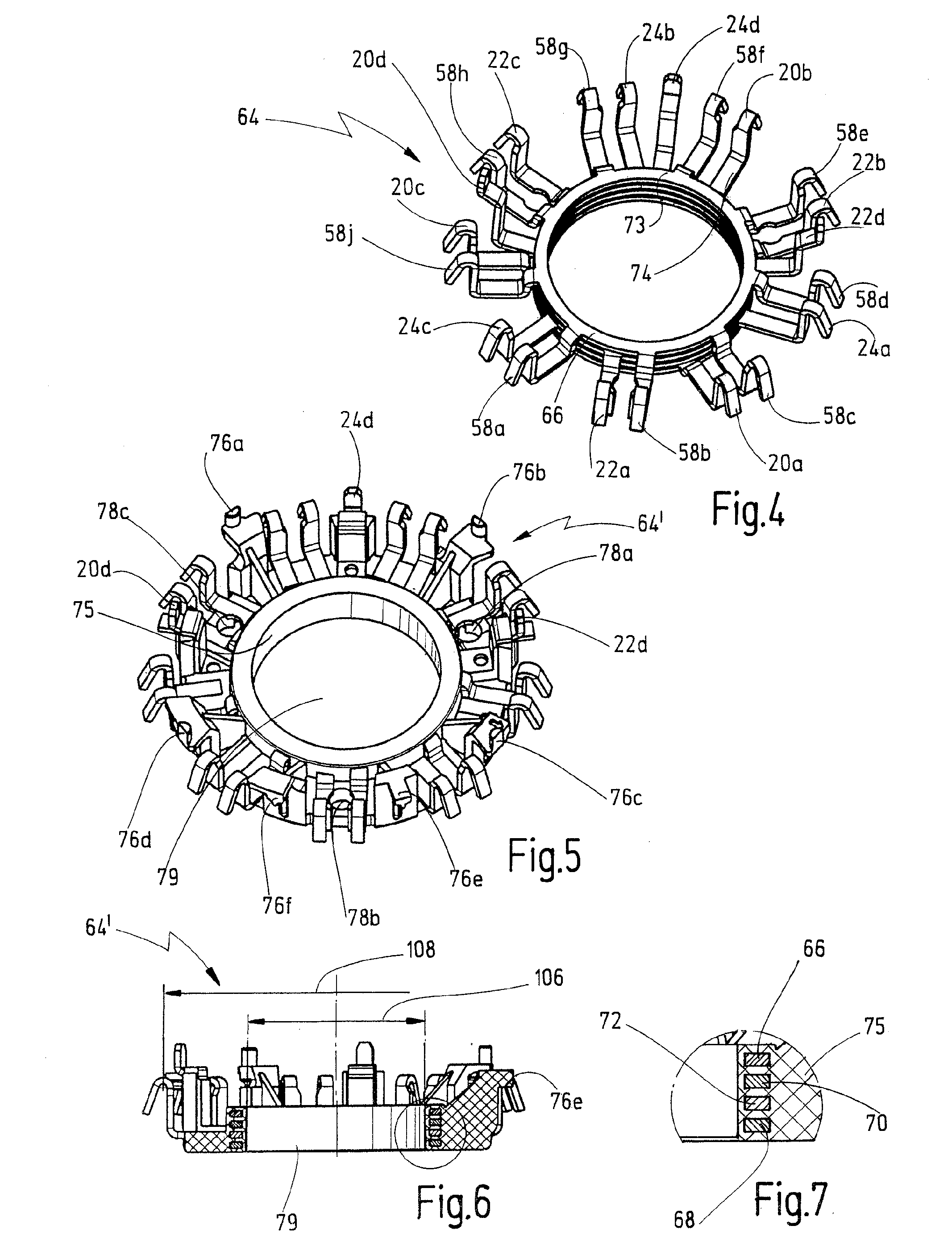
[0106]The hand-held tool 10 has a housing 12 in which a drive 14 is held, with an electric motor 16 and a motor controller 18. By way of example, the electric motor 16 has three contacts 20, 22, 24, via which, for example, current can be passed through three winding phases U, V, W. This may therefore be an electric motor to which a rotating field is applied and which is provided with a rotor with permanent-magnet excitation.

[0107]The motor controller 18 is designed to apply the alternating field to the phases of the motor U, V, W. This type of excitation may be electronic commutation. The alternating field may in this case have a sinusoidal waveform, may be in block form or else may have a pulse-width modulated signal waveform in block form, by means of which it is possible to approximate to a sinusoidal waveform.

[0108]The motor controller 18 is coupled to a power supply device 30 via supply lines...


PUM

PropertyMeasurementUnit
Diameteraaaaaaaaaa
Diameteraaaaaaaaaa
Electrical conductoraaaaaaaaaa

Abstract

An electric motor, in particular a motor which can be commutated electronically, is disclosed. The motor comprises a stator with a plurality of field windings which are wound at least in places from a winding wire, and further comprises a contact grid for making contact with the field windings, which contact grid has a plurality of conductor tracks which are insulated from one another, with the conductor tracks having contacts to which the winding wire is fixed, wherein the winding wire is cut through between specific contacts such that this results in the field windings being connected in a manner which is suitable for generating a rotating field when being powered by a suitable motor controller.

Description

CROSSREFERENCES TO RELATED APPLICATIONS[0001]This application claims priority from German patent application 10 2010 025 261.1, filed on Jun. 23, 2010, the entire contents of which is incorporated herein by reference.BACKGROUND OF THE INVENTION[0002]The invention relates to an electric motor, in particular a motor which can be commutated electrically for a hand-held tool having a stator with a plurality of field windings which are wound at least in places from a winding wire, having a contact grid for making contact with the field windings, which contact grid has a plurality of conductor tracks which are insulated from one another, with the conductor tracks having contacts to which the winding wire is fixed.[0003]The invention furthermore relates to a method for production of an electric motor.[0004]An electric motor such as this is known from WO 2002 / 087057 A1.[0005]The known electric motor is an electronically commutated direct-current motor having a stamped grid on which contact ...

Claims


Application Information

Patent Timeline
IPC IPC(8): H02K3/28H02K15/00
CPCH02K3/50Y10T29/49009H02K2203/09
Inventor DIETL, LOTHARHOKENMAIER, TOBIASMAIER, CHRISTOPH
Owner C & E FEIN
Why Eureka
Try Eureka