
System and method for tuning-capacitor-array sharing

a technology of capacitor array and tuning circuit, applied in the field of radio frequency system, can solve the problems of more difficult design and interference with intended signals

Active Publication Date: 2011-12-29
QUINTIC MICROELECTRONICS WUXI
View PDF2 Cites 12 Cited by
  • Summary
  • Abstract
  • Description
  • Claims
  • Application Information

AI Technical Summary

Benefits of technology

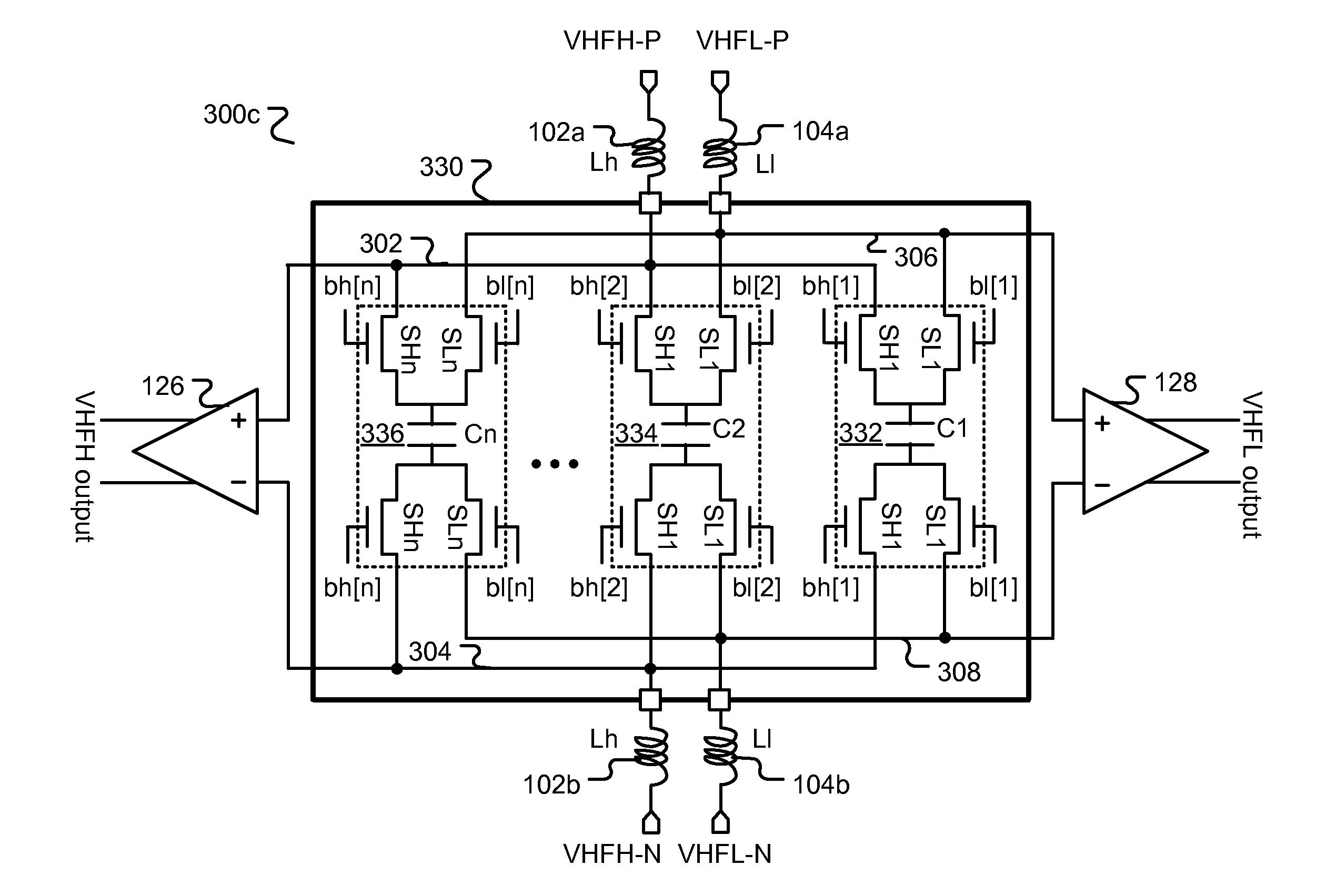
[0005]According to one embodiment of the present invention, a device to provide two tuning circuits to share an adjustable capacitance device is disclosed. The device comprises at least one first tuning component coupled to a first node, at least one second tuning component coupled to a second node, and at least one variable capacitance device configured to selectively couple to one of the first node and the second node according to mode control. The said at least one first tuning component and said at least one variable capacitance device form a first tuning circuit when the mode control causes said at least one variable capacitance device to couple to the first node, and said at least one second tuning component and said at least one variable capacitance device form a second tuning circuit when the mode control causes said at least one variable capacitance device to couple to the second node. Furthermore, said at least one variable capacitance device comprises a digitally programmable switched capacitor array configured to adjust tuning frequency of one of the first tuning circuit and the second tuning circuit according to the mode control. The tuning frequency is adjusted in response to a plurality of first tuning control signals for the first tuning circuit and in response to a plurality of second tuning control signals for the second tuning circuit, and the plurality of first tuning control signals and the plurality of second tuning control signals are generated by a digitally programmable control register.
[0006]In another embodiment of the present invention, said digitally programmable switched capacitor array comprises a plurality of capacitor sections coupled in parallel. Furthermore, each of the plurality of capacitor sections comprises a fixed capacitor, said digitally programmable switched capacitor array further comprises a plurality of first transistors and a plurality of second transistors, each of the plurality of first transistors being coupled in series with the first node and the fixed capacitor in a respective one of the plurality of capacitor sections, each of the plurality of second transistors being coupled in series with the second node and the fixed capacitor in a respective one of the plurality of capacitor sections, and wherein each of the plurality of first tuning control signals controls a respective transistor in the plurality of first transistors and each of the plurality of second tuning control signals controls a respective transistor in the plurality of second transistors. In yet another embodiment of the present invention, the plurality of first tuni...

Problems solved by technology

In a real radio environment, there are many un-intended signals which may interfere with an intended signal if the un-intended signals are not properly processed.
When the tunable range is beyond 20% of the carrier frequency, it will make the design more challenging.

Method used


Image

  • System and method for tuning-capacitor-array sharing
  • System and method for tuning-capacitor-array sharing
  • System and method for tuning-capacitor-array sharing

Examples


Embodiment Construction

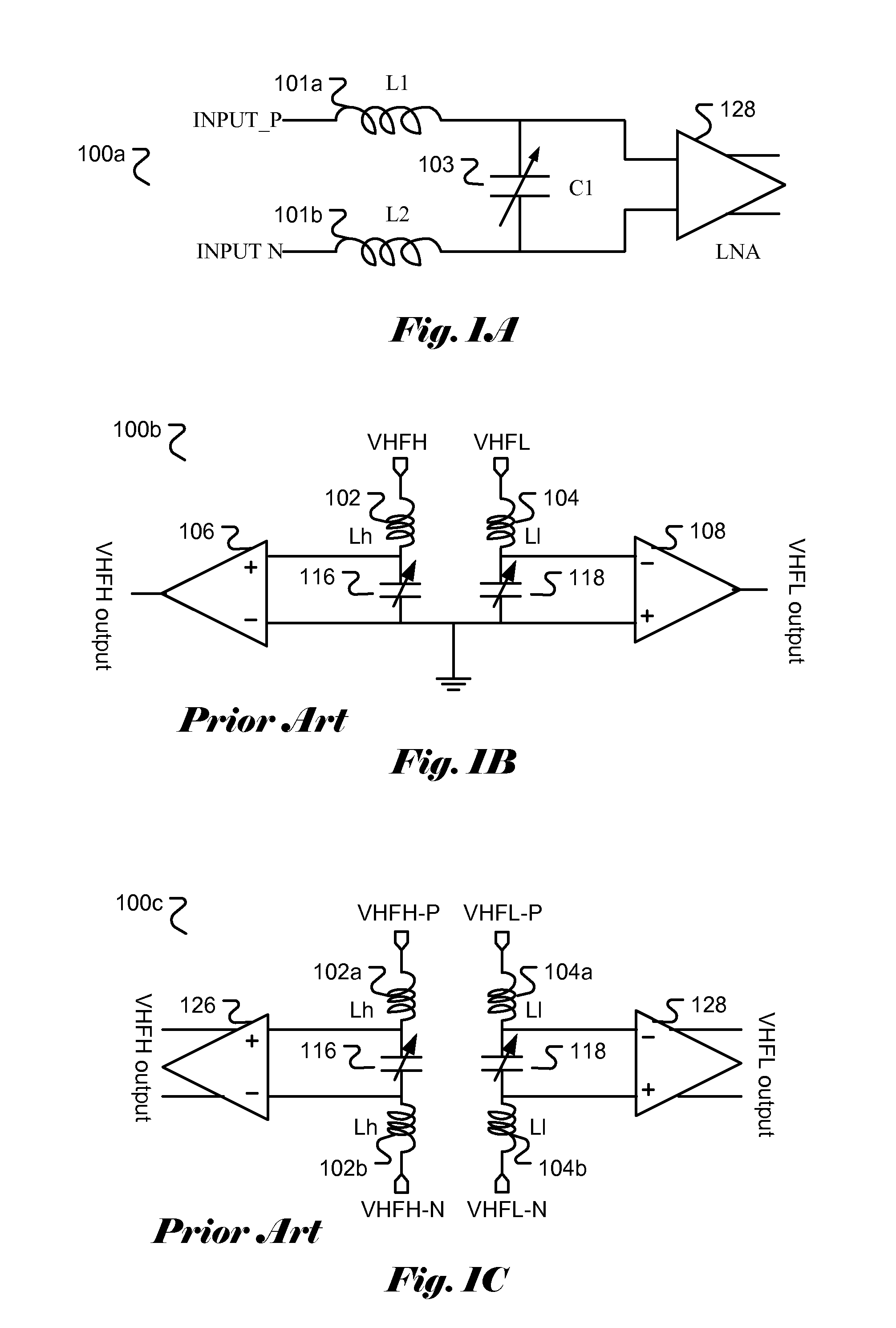
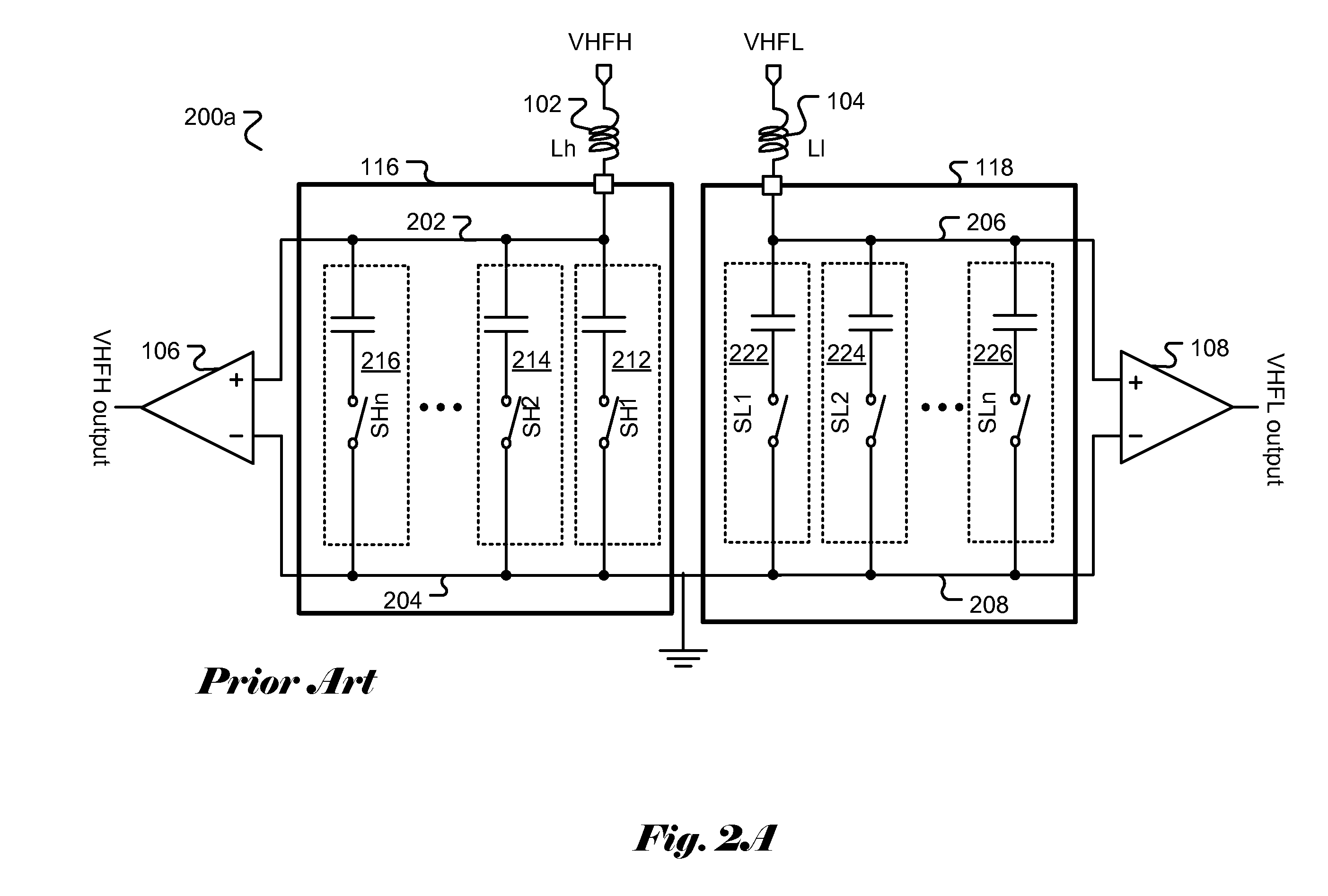
[0019]In a radio receiver, a tuning circuit is often used in various stages of the receive path to allow the passage of intended signals while attenuate the undesired signals. For example, a tuning circuit may be used in the RF stage along with a low-noise amplifier (LNA) so that only the intended signal will be passed and amplified. A properly designed tuning circuit will effectively reject out of band signals that may potentially result in image signals of an intended signal. Depending on the intended application, the tuning circuit has to support a range of tunable frequencies. For example, a terrestrial broadcast TV receiver, the tuning circuit has to support TV channels in the low VHF band (such as 44-92 MHz in the US), the high VHF band (such as 167-230 MHz in the US) and the UHF band (such as 470-860 MHz in the US). In general, a wider tunable-range circuit is harder to design than a narrower tunable-range circuit. In practice, the tunable range is maintained to be less than ...


PUM


Abstract

A system and method for sharing a switched capacitor array (SCA) by two tuning circuits are disclosed. In a multiple-band radio receiver, there is a need to use multiple tuning circuits for signals in different bands. The tuning circuit typically comprised an adjustable capacitance device and other tuning components, where the adjustable capacitance device is often implemented in SCA. The present invention discloses a system and method comprising n sections of capacitor elements where each capacitor element comprises a capacitor and switches to selectively connect the capacitor to one of the tuning circuit. Consequently, the SCA can be shared by the two tuning circuits. The control bits for the switched may be provided from a programmable control register.

Description

FIELD OF THE INVENTION[0001]The present invention relates to radio frequency system. In particular, the present invention relates to tuning circuits for multiple-band system to share a programmable switched capacitor array.BACKGROUND[0002]In a radio receiver, a radio frequency (RF) signal is typically received using an antenna and the received RF is then processed along the receive path to recover the original signal transmitted. In the receive path, the received signal is subject to various processing such as amplifying, filtering, down-converting, demodulating, and etc. In a real radio environment, there are many un-intended signals which may interfere with an intended signal if the un-intended signals are not properly processed. By using a tuning filter is one effective means to block un-intended signals to ensure the quality of final received signal. In a radio transmitter, it also provides some advantage to use a tuning filter to suppress out-of-band signals which may be genera...

Claims


Application Information

Patent Timeline
IPC IPC(8): H03J5/24
CPCH03J2200/10H03J5/244
Inventor MENG, HAOXUAN, PEIQI
Owner QUINTIC MICROELECTRONICS WUXI
Learn More