

Winding arrangement for a transformer or for a throttle
a winding arrangement and transformer technology, applied in transformers/inductances magnetic cores, inductances with magnetic cores, inductances, etc., can solve the problems of transformer or reactor operation behavior, noise during transformer operation, and special risk to the conductors of the winding located at the end fa
- Summary
- Abstract
- Description
- Claims
- Application Information
AI Technical Summary
Benefits of technology
Problems solved by technology
Method used
Image

Examples
Embodiment Construction
[0009]The invention is based on the object of disclosing a winding arrangement for a transformer or for a reactor such that the operating behavior is improved as simply as possible and the winding is effectively electrostatically protected.
[0010]This object is achieved by a winding arrangement with the features of the claims. Advantageous developments of the invention are defined in the dependent claims.
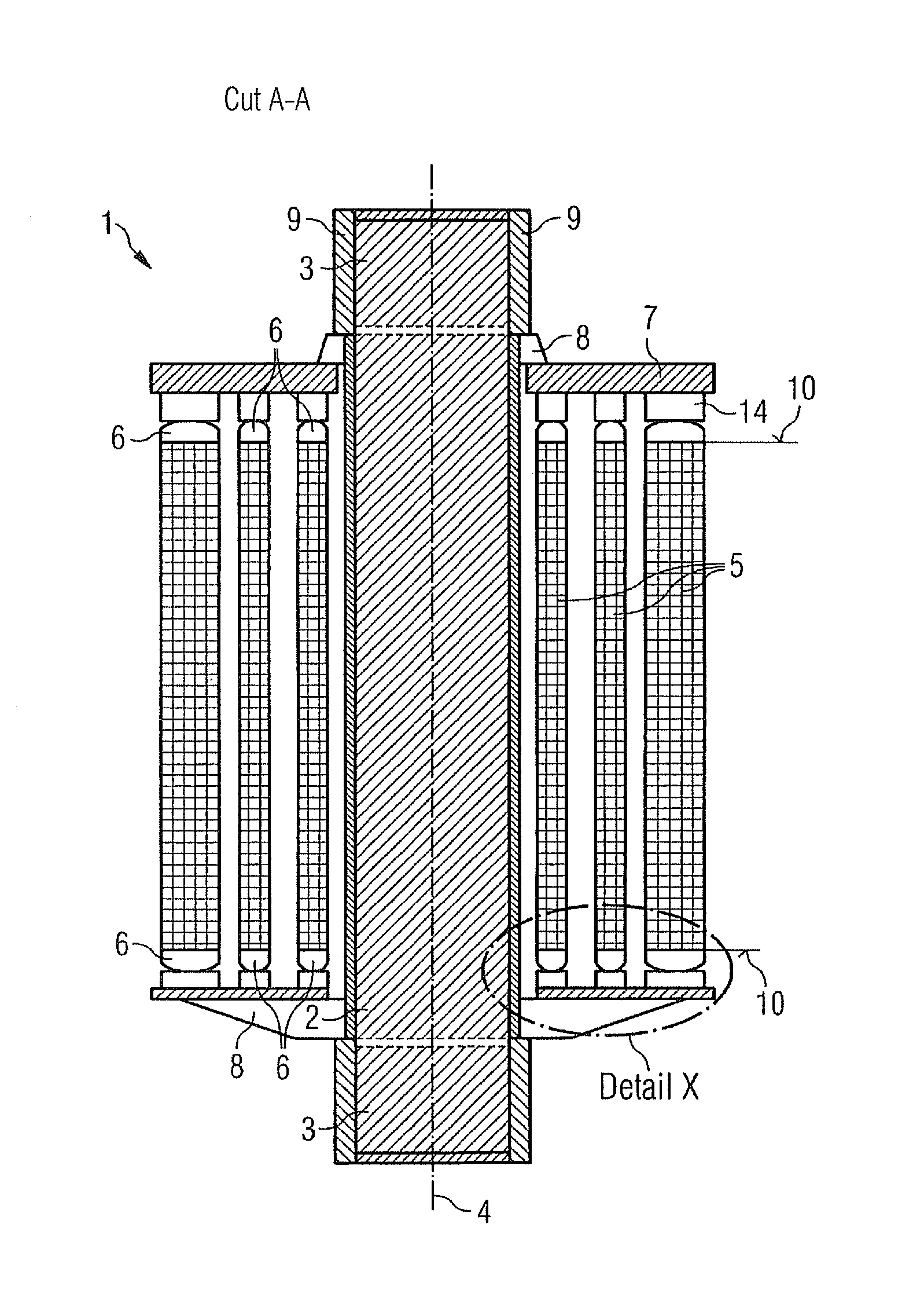
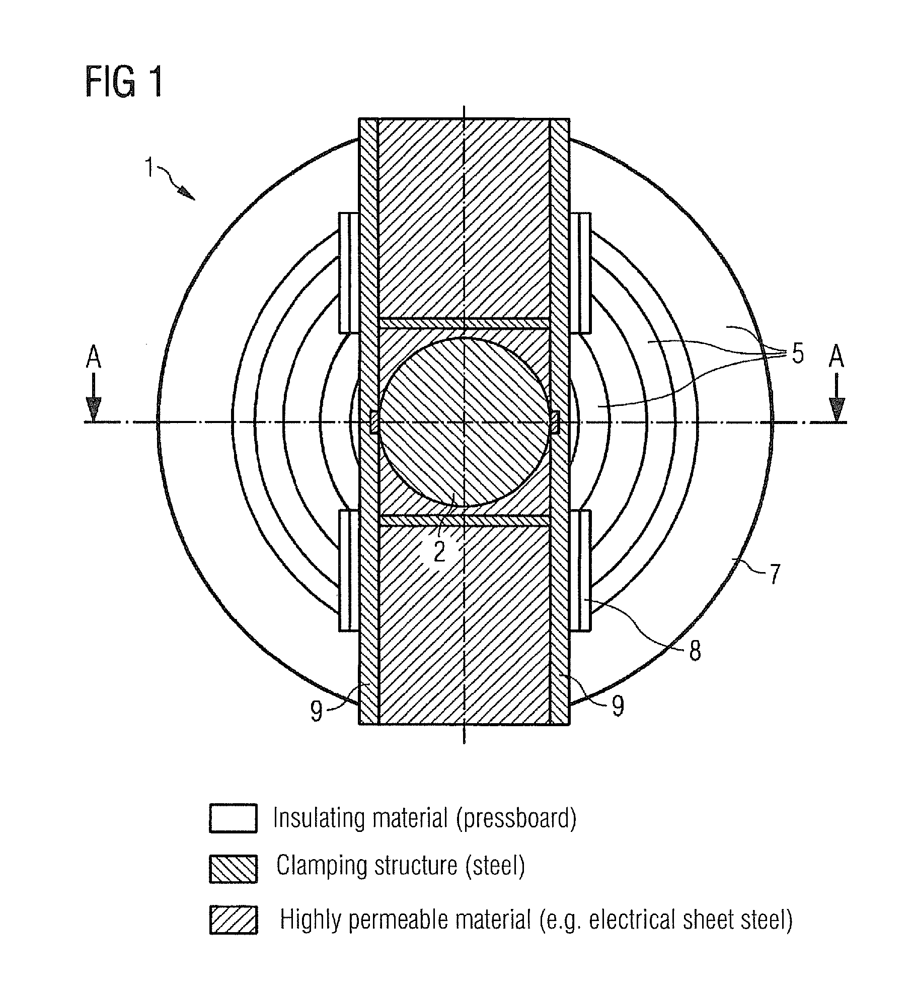
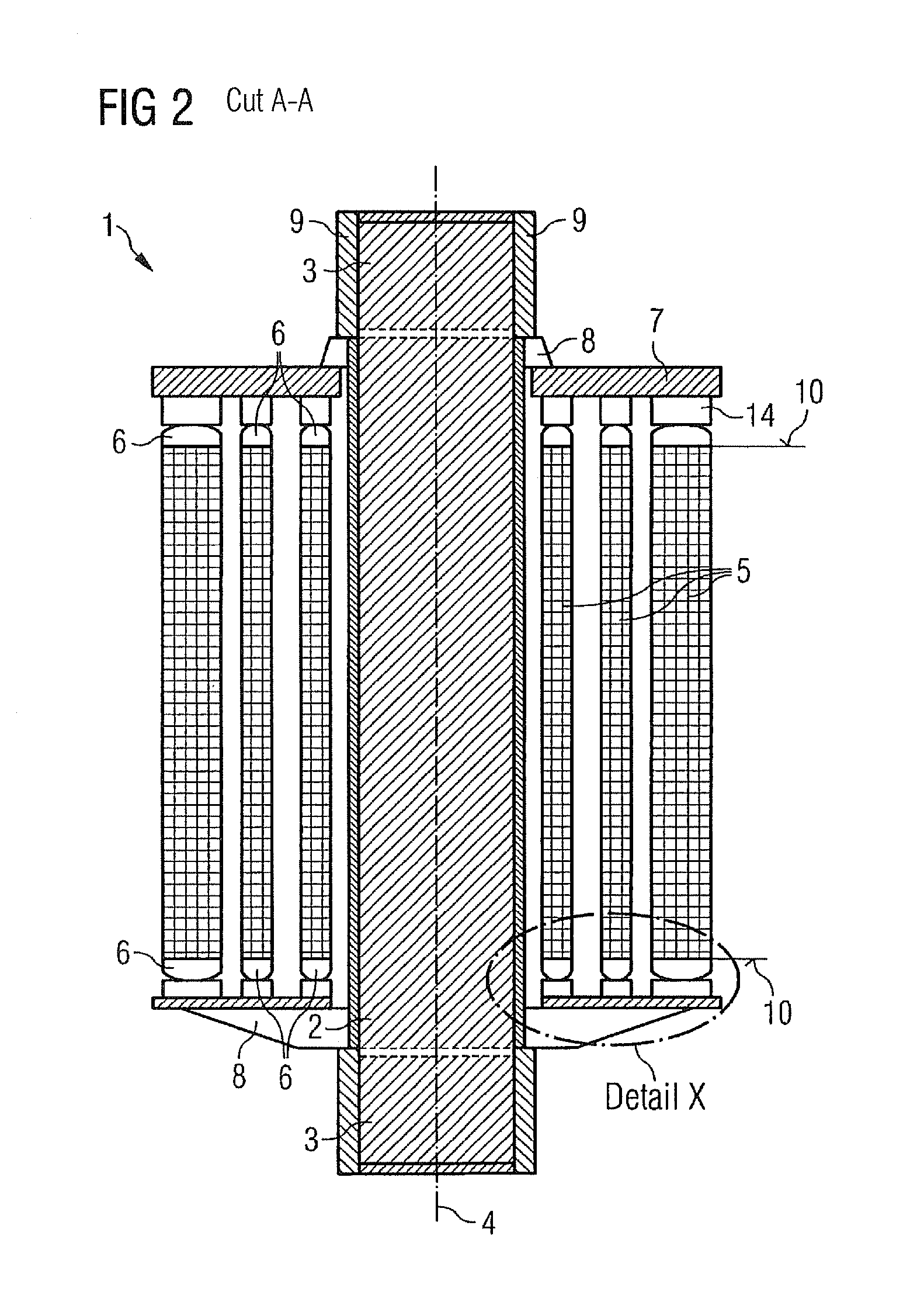
[0011]At each end face of a winding the inventive winding arrangement comprises an annular winding cover part which is designed so as to be magnetically conductive at least in a partial area and comprises a convex side surface facing away from the winding. These two design features, the magnetic conductivity and the domed side surface, cooperate so as to promote a reduction in noise and an electrostatic protective effect.
[0012]The magnetically conducive design of the winding cover part firstly means that the magnetic field in the end region of the winding is guided in an axial direct...
PUM
| Property | Measurement | Unit |
|---|---|---|
| magnetically conductive | aaaaa | aaaaa |
| electrically conductive | aaaaa | aaaaa |
| insulating | aaaaa | aaaaa |
Abstract
Description
Claims
Application Information