Supercharge Your Innovation With Domain-Expert AI Agents!

Micro-ejector

a micro-ejector and ejector body technology, applied in printing and other directions, can solve the problems of increasing manufacturing costs, and reducing the efficiency of ejection, so as to prevent the leakage of fluid

Inactive Publication Date: 2011-12-29
SAMSUNG ELECTRO MECHANICS CO LTD
View PDF2 Cites 2 Cited by
  • Summary
  • Abstract
  • Description
  • Claims
  • Application Information

AI Technical Summary

Benefits of technology

The present invention provides a micro-ejector with a power supplying line and piping system for supplying fluid, which reduces manufacturing costs and allows for one-time use of multiple ejection devices. The micro-ejector includes an ejection device with a piezoelectric actuator for ejecting fluid, a mounting plate with a passage for providing fluid to the ejection device, and a connection member for connecting the piezoelectric actuator to an external power source. The mounting plate may also include an elastic member for close fitting the ejection device, a thermoelectric element for heating or cooling the fluid, and a cooling passage for cooling the thermoelectric element. The micro-ejector may also have a tightening device for adjusting the pressing force between the support plate and the passage plate, a fluid inflow hole, a pressure chamber, a nozzle part, and a sealing member to prevent leakage of fluid.

Problems solved by technology

As for the micro-ejector using the piezoelectric element, a connection line for applying power to the piezoelectric element from an external power source and a piping system supplying fluid such as fluid containing samples and the like, to an ejection device may need to be provided, which causes an increase in manufacturing costs, and therefore the ejection device may need to be cleansed and reused, resulting in an increase in a possibility of cross-contamination of the fluid such as fluid containing samples and the like, and a reduction in ejection-operational efficiency.

Method used


Image

  • Micro-ejector
  • Micro-ejector
  • Micro-ejector

Examples


Embodiment Construction

[0027]Exemplary embodiments of the present invention will now be described in detail with reference to the accompanying drawings. However, it should be noted that the spirit of the present invention is not limited to the embodiments set forth herein and those skilled in the art and understanding the present invention can easily accomplish retrogressive inventions or other embodiments included in the spirit of the present invention by the addition, modification, and removal of components within the same spirit, and those are to be construed as being included in the spirit of the present invention.

[0028]Further, throughout the drawings, the same or similar reference numerals will be used to designate the same components or like components having the same functions in the scope of the similar idea.

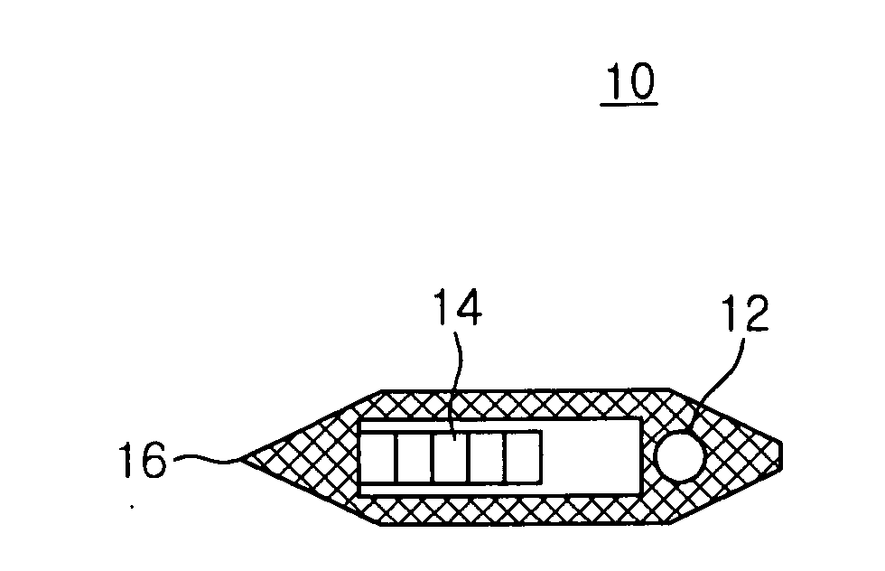
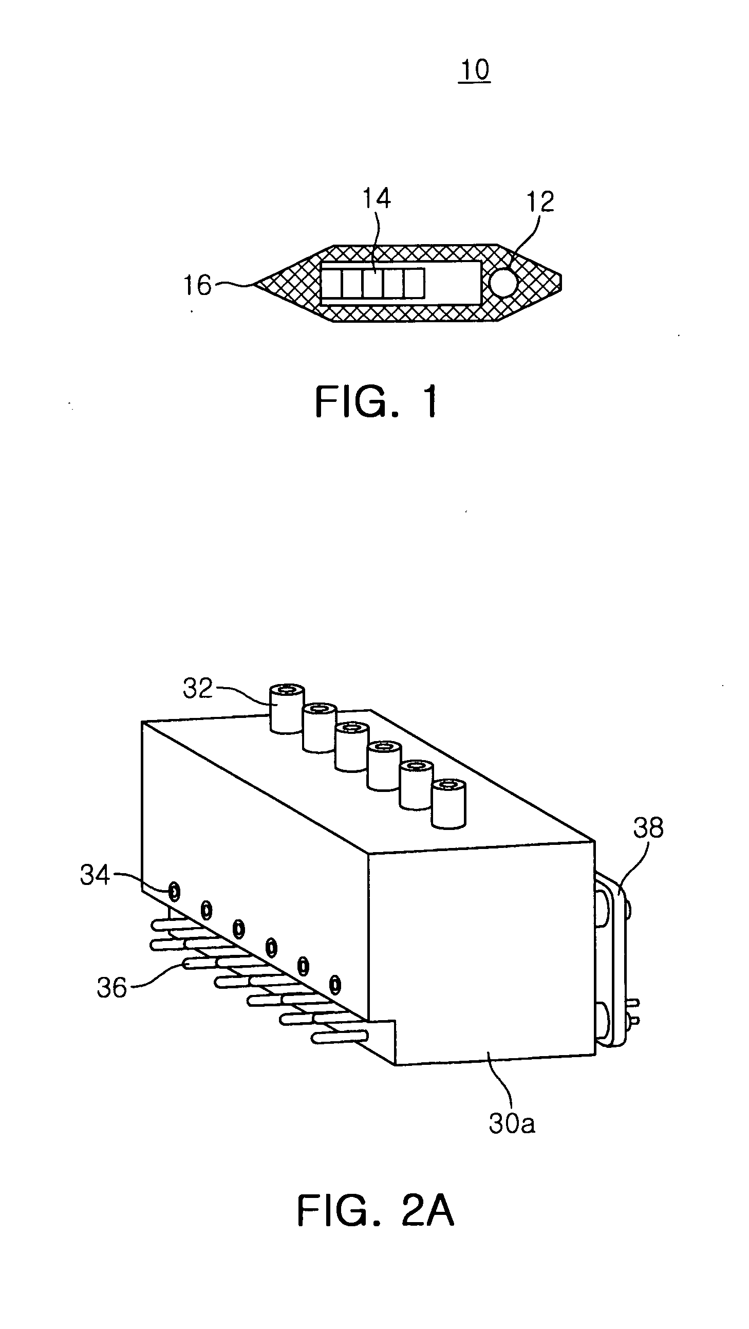
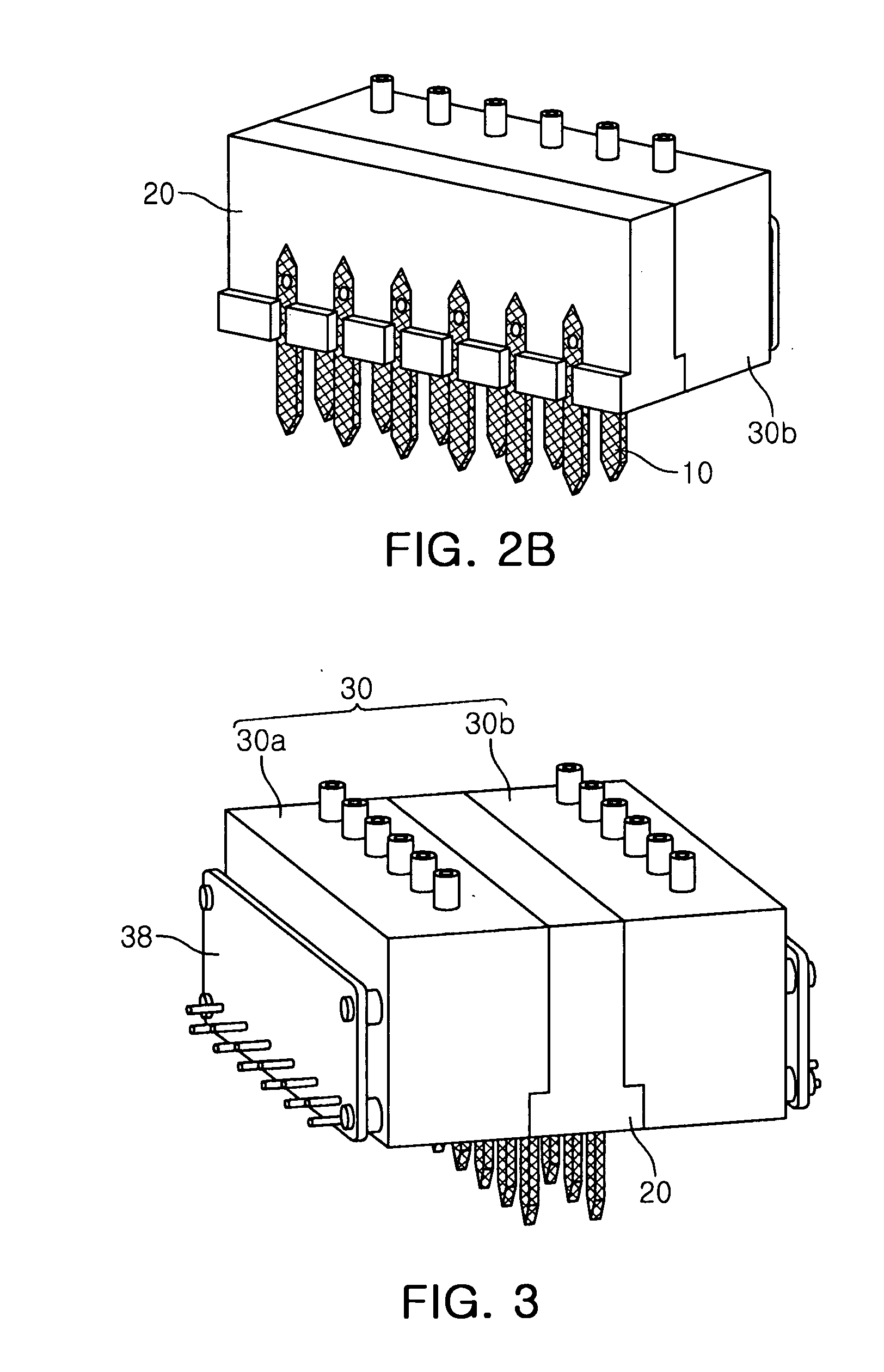
[0029]FIG. 1 is a view showing a configuration of an ejection device in a micro-ejector according to an exemplary embodiment of the present invention, FIGS. 2A and 2B are views showing a stru...


PUM


Abstract

There is provided a micro-ejector. The micro-ejector according to an exemplary embodiment of the present invention may include an ejection device including a passage for ejecting fluid contained therein, and a piezoelectric actuator providing a driving force for ejecting fluid, a mounting plate including a passage for providing fluid to the ejection device formed therein, and a mounting groove on which the ejection device is mounted, and a connection member formed on the mounting plate, and adopted for connecting the piezoelectric actuator to an external power source.

Description

CROSS-REFERENCE TO RELATED APPLICATIONS[0001]This application claims the priority of Korean Patent Application No. 10-2010-0061436 filed on Jun. 28, 2010, in the Korean Intellectual Property Office, the disclosure of which is incorporated herein by reference.BACKGROUND OF THE INVENTION[0002]1. Field of the Invention[0003]The present invention relates to a micro-ejector, and more particularly, to a micro-ejector, in which a structure of a power line applying power to a piezoelectric element and a structure of a fluid supplying line supplying fluid to an ejection device may be simplified so as to eject minute droplets using the piezoelectric element, thereby reducing manufacturing costs, and which is capable of realizing one-time use of the ejection device.[0004]2. Description of the Related Art[0005]The field of bio-technology, among highly developed modern high technologies, has recently received a great deal of attention. In general, since many biological samples used in bio-techno...

Claims


Application Information

Patent Timeline
Patent Type & Authority Applications(United States)
IPC IPC(8): B41J2/045
CPCB41J2002/14362B41J2/14233
Inventor KIM, SANG JINKIM, CHANGSUNG SEANSONG, SUK HO
Owner SAMSUNG ELECTRO MECHANICS CO LTD
Features
  • R&D
  • Intellectual Property
  • Life Sciences
  • Materials
  • Tech Scout
  • Unparalleled Data Quality
  • Higher Quality Content
  • 60% Fewer Hallucinations
Learn More